nRF24L01 Module
Schematics can be found [here]
The nRF24L01 module...
- Module ID: 15
- IN_A:
- IN_B:
- IN_C:
- IN_D: ID - Used to set the module ID
- IN_E:
- IN_F:
- IN_G:
- IN_H:
- OUT_A:
- OUT_B:
- OUT_C:
- OUT_D:
The board is 2 layer, 23.5x28 mm.
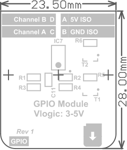
Homepage
Pictures
GUI Mockup
Contact
Version 2:
ui-processor-rtos
fpga-config-mcu
fpga-config-over-uart
Version 1:
freertos-serial-monitor
freertos-serial-monitor lcd test
Simple GUI:
General
GUIObject
GUIButton
GUILabel
GUIStaticTextBox
GUIAlertBox
GUIButtonGridBox
GUIButtonList
GUIInfoBox
Tasks:
LCD Task Message
LCD:
LCD ER-TFT070-4
LCD ER-TFTM070-5
LCD HY070CTP-HD
LCD HY101CTP-HD
LCD YL070MY01
Touch Controller
Measurements:
STM32 GPIO Speed
FT5206 Waveform Capture
Version 2:
Revision 2 Mockup
Module IDs
Boards:
Connection Board
UI Processor Board
Data Processor Board
Isolated Power Module
LCD Board
Modules:
1. GPIO Module
3. CAN Module
5. RS-232 Module
15. nRF24L01 Module
Future Module Ideas
FPGA:
FPGA Main Blocks
FPGA Communication
FPGA UART
FPGA GPIO
FPGA Timestamp
FPGA SDRAM
FPGA PLL
[FPGA ID Reader](https://github.com/hampussandberg/HexConnect/wiki/FPGA-ID Reader)
FPGA LVDS
FPGA Monitor
FPGA Tips and Tricks
Learning Quartus II
Version 1:
Requirement Specification
Hardware Design
Hardware Rev 1 Fixes