Simple GUI
TODO: Update with newest version of the files
As the Serial Monitor will have a lot of graphical elements displayed on the screen I created a GUI library to manage all these elements.
FILES: Source, Header, Config
The basic principle behind Simple GUI is that each element has an unique ID that is used when the element is changed or accessed in some way. To make things simple Simple GUI includes a config file that you have to create where all the ID's are defined. An example of such a file can be found here
With the move to the STM32F429 processor I decided to rethink the layer management which was non-existent in the previous version. The LTDC-controller in the STM32F429 has hardware support for two layers that can be switched between however you want but I wanted something more flexible with more layers and blending. Fortunately there is another great hardware in the STM32F429 called Chrom‑ART Accelerator or DMA2D. This is a 2-dimensional DMA unit which can blend pixels together and convert between different color formats and it is really simple to use. ST provides a couple of examples on how to use the DMA2D which can be found when downloading the standard libraries.
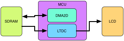
There are some things that are needed to make this layer management work. First is a place to store the data for the different layers. This is preferably done using the SDRAM-controller connected to a SDRAM at a decent size. The STM32F429 Discovery Board that I'm using has 64 Mbits of SDRAM which is plenty. The memory is also used by the LTDC-controller as a buffer for the screen which means that to display something on the screen all you have to do is write data at the correct place in the SDRAM.
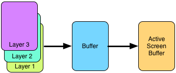
Each layer has it's own space in the memory and can be written to without affecting the other layers at all, which is what we want. When we want to refresh the screen we basically just copy the data from one layer at a time (start with the one at the bottom) to the buffer and blend everything together each time. This means that we need transparency in the pixel data besides the color, this is done using ARGB8888 color format for each layer. When all layers have been moved to the temporary buffer we can move this buffer to the active screen buffer. The reason to do this extra step is to avoid flickering on the screen. By doing the blending of each layer and saving the result in a temporary place it can be done behind the scenes so to say and only the result will be viewable on the screen. If we were to write to the active screen buffer immediately we would see the screen flickering and some times we would see object half-drawn which would be ugly.
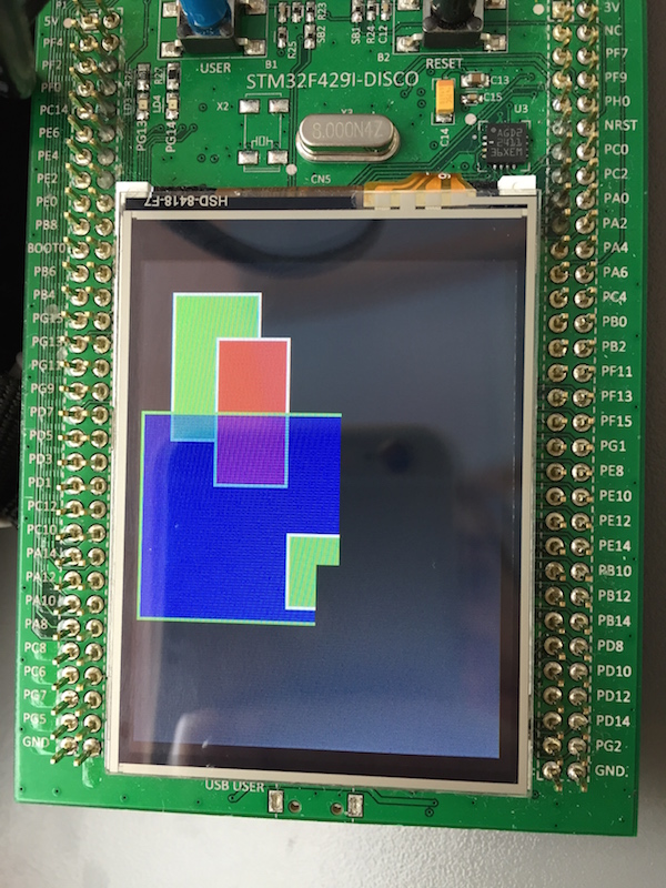
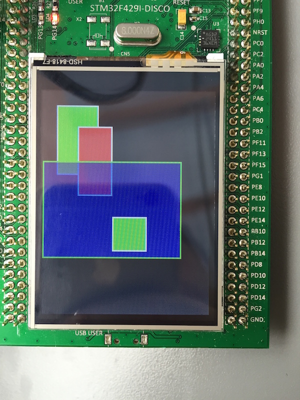
A program testing the layer capabilities can be seen below. Here there are 3 active layers shown on the screen. Layer 1 contains the tall green square and a black background. Layer 2 contains the red square and layer 3 has the semi-transparent blue square and the small green square.
One problem we have now is that if something is changed on a layer we need to do this copy and blending for the whole screen and with all layers. A better way of dealing with this is what I call "dirty zones". Whenever Simple GUI updates an object, let's say a button is pressed and the color should change, it will check what parts of the screen are contaminated, i.e. dirty. The screen is divided into a coarse grid (size can be adjusted depending on the application) where each square is a zone. When an object is updated a function checks which zones the object is part of and mark them as dirty. At a later point when it's time to refresh the screen we only need to check which zones are dirty and then to the copy and blending for those smaller squared zones. This improved the speed quite a lot even on the 320x240 screen used on the STM32F420 Discovery Board, which implies that on the HexMon serial monitor with it's 800x480 screen there should be a significant improvement as well.
TODO: Image explaining dirty zones
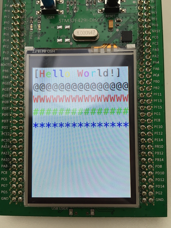
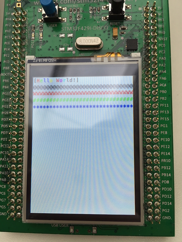
Below is a photo showing the dirty zone redrawing in action (this is usually not visible but can be activated in the code for easier debugging). The green square has not been fully drawn yet as it takes care of one zone at a time.