FPGA UART
The UART module on the FPGA should be able to send and receive data, i.e. we need a transmitter and a receiver. Together they form a UART Transceiver.
As both RS-232 and "regular" 5V/3.3V UART is the exact same protocol (only the voltages are different) and the different modules on the HexMon takes care of the voltage translations, we can use the UART module for both of these.
As UART has no clock signal we have to take care of timing in some other way. A simple way that always was mentioned when doing a quick search on the web was oversampling. It means that you read the input faster than it is actually changing. For example if we have a UART at 9600 bits/s and use 16x oversampling we will have a sample tick that is 16*9600 = 153600Hz.
As can be seen in the simulation image below, for each input bit there are 16 tick pulses. Even though it's hard to see in the image the clk signal from which the tick is generated is a lot faster. In this example clk is 100MHz. That means, to get a 153600Hz tick we have to wait 100MHz / 153600Hz 651,04166... ≈ 651 clk cycles. The tick generator is basically a counter that, depending on the selected baud rate, will count to a specific number (651 for example) and then toggle the tick signal for one clk cycle.
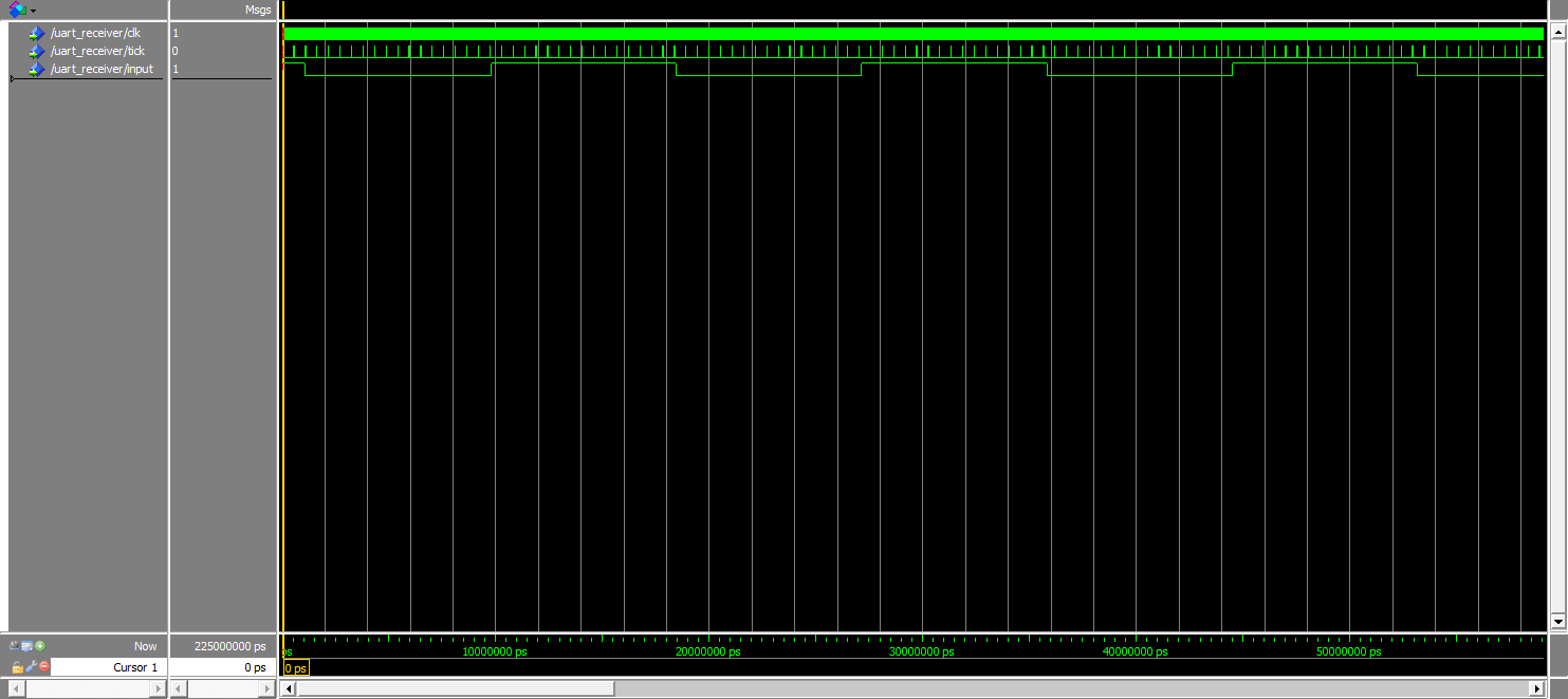
UART Tick simulation
I learned this the hard way... After first simulating a test receiver for the UART I thought everything should work just fine and it did for the most part of it. The problem was that sometimes when sending a lot of data after each other to the UART receiver on the FPGA from an external FT232RL chip the byte that was read by the FPGA would be wrong. This didn't happen all the time but it was enough for it to make the receiver useless (random wrong data is not good).
After some thinking I came to the conclusion that it had to be some problem with the stop bit and that the FT232RL I was using together with CoolTerm was not generating it correctly. I simulated the "error" by making the stop bit smaller than it should be, as can be seen at the cursor in the image below. This seemed to give the same error as I could see on the FPGA board sometimes (the output being "1111 0101"), but if this was the true cause of the error it meant nothing was wrong with my design. Unfortunately I didn't have access to an oscilloscope so I couldn't verify if the stop bit actually was too short or not.
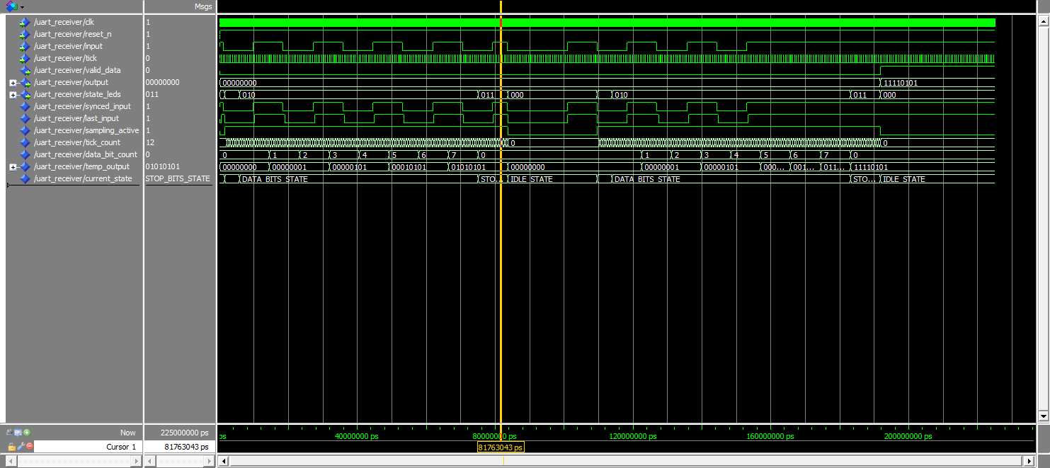
Bad stop bit simulation
After some more Googling I found this post on StackExchange (http://electronics.stackexchange.com/questions/137194/uart-receiver-glitches). It didn't really relate to my problem but there was one word in the post that got me thinking, asynchronous.
The input signal in my design is directly connected to the output pin of the FPGA and this means that it's completely asynchronous compared to the rest of the design. I was using this signal at a couple of places in the VHDL code that were synchronous which meant that the signal was not stable at all in relation to the other signals used. The solution was as simple as making an internal copy of the input signal called synced_input this is updated with the value of input on each rising edge of the clock.
A "quick" synthesize and programming of the FPGA showed that IT WORKED!!! Of course doing the same simulation as in the image above will still render the same error of the output. That is because the problem didn't have anything to do with the length of the stop bit which means the simulation is basically useless. When I come to think about it, I have heard/read that you should always synchronize your input signals to avoid problem, but I guess I had to learn it the hard way.
Found some more information about this here: http://www.doulos.com/knowhow/fpga/synchronisation/
In the receiver, which is clocked by the main clock, on each rising edge it will check if the tick signal has a rising edge. That indicates that a tick has occurred and the receiver should take action. To make things organized a finite state machine (FSM) is used with the states seen below. Transition from one state to another can only be done on a tick.
- IDLE_STATE
- START_BIT_STATE
- DATA_BITS_STATE
- PARITY_BIT_STATE
- STOP_BITS_STATE
A simulation of a UART frame can be seen below with the state transitions. Here we receive on the input one start bit, eight data bits (1010 1010), no parity bit and one stop bit.
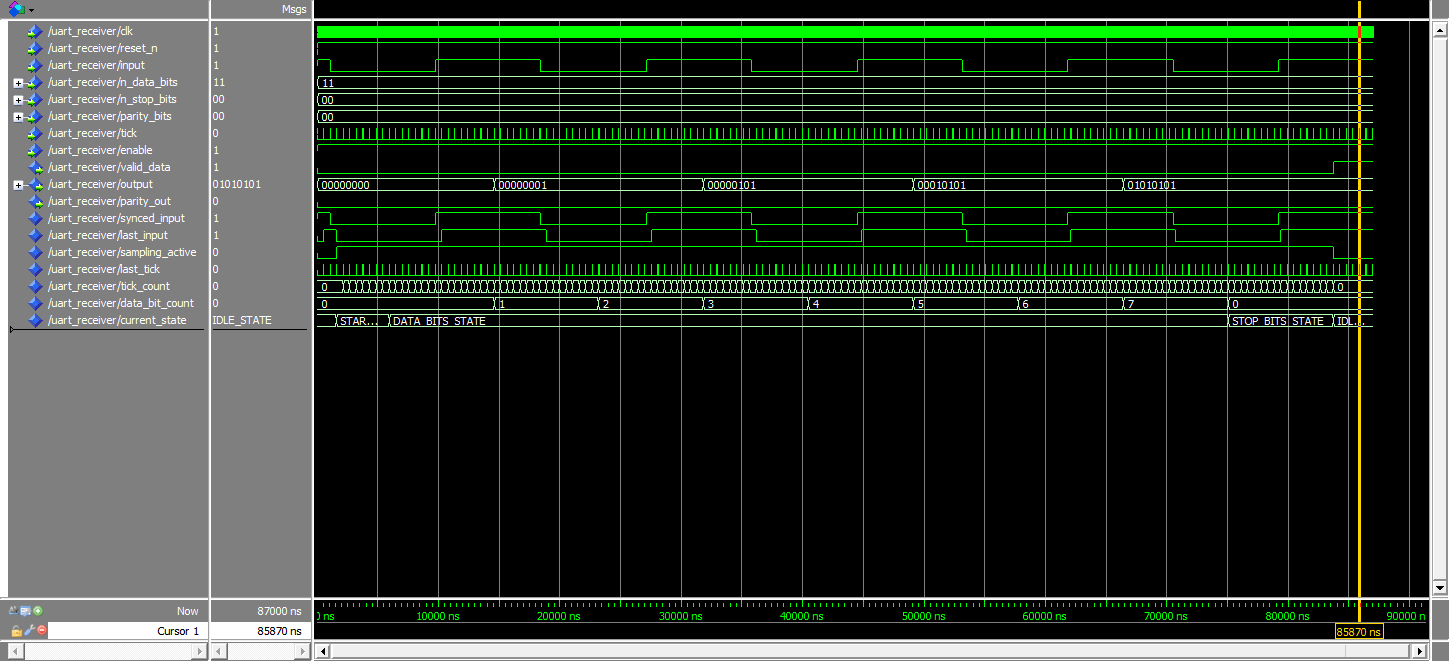
UART Receiver Simulation
As data bits are sampled by the receiver they are set on the output signal and when a valid stop bit is received the valid_data signal is set to notify the user of the receiver. As the UART data rate is much slower than the clock rate of the FPGA modules there should be enough time for the user to read the data that has been received before a new data frame is started. If for some reason the user do not take action before a new data frame the valid_signal will go low again and the output will be cleared.
As an example: we have a UART baud rate of 115200 bits/second and an internal frequency on the FPGA of 100MHz. This means that each UART bit is ~8680ns long, which is the same as ~868 clock cycles on the FPGA. But we also has to remember that the receiver is sampling in the middle of the UART bits so we have to cut the time we have in half, i.e. we have ~4340ns to react which is 434 clock cycles @ 100MHz. If this is a problem we could always increase the internal clock frequency.
The transmitter is very similar to the receiver which makes sense as they both deal with UART data frames. The same states are used:
- IDLE_STATE
- START_BIT_STATE
- DATA_BITS_STATE
- PARITY_BIT_STATE
- STOP_BITS_STATE
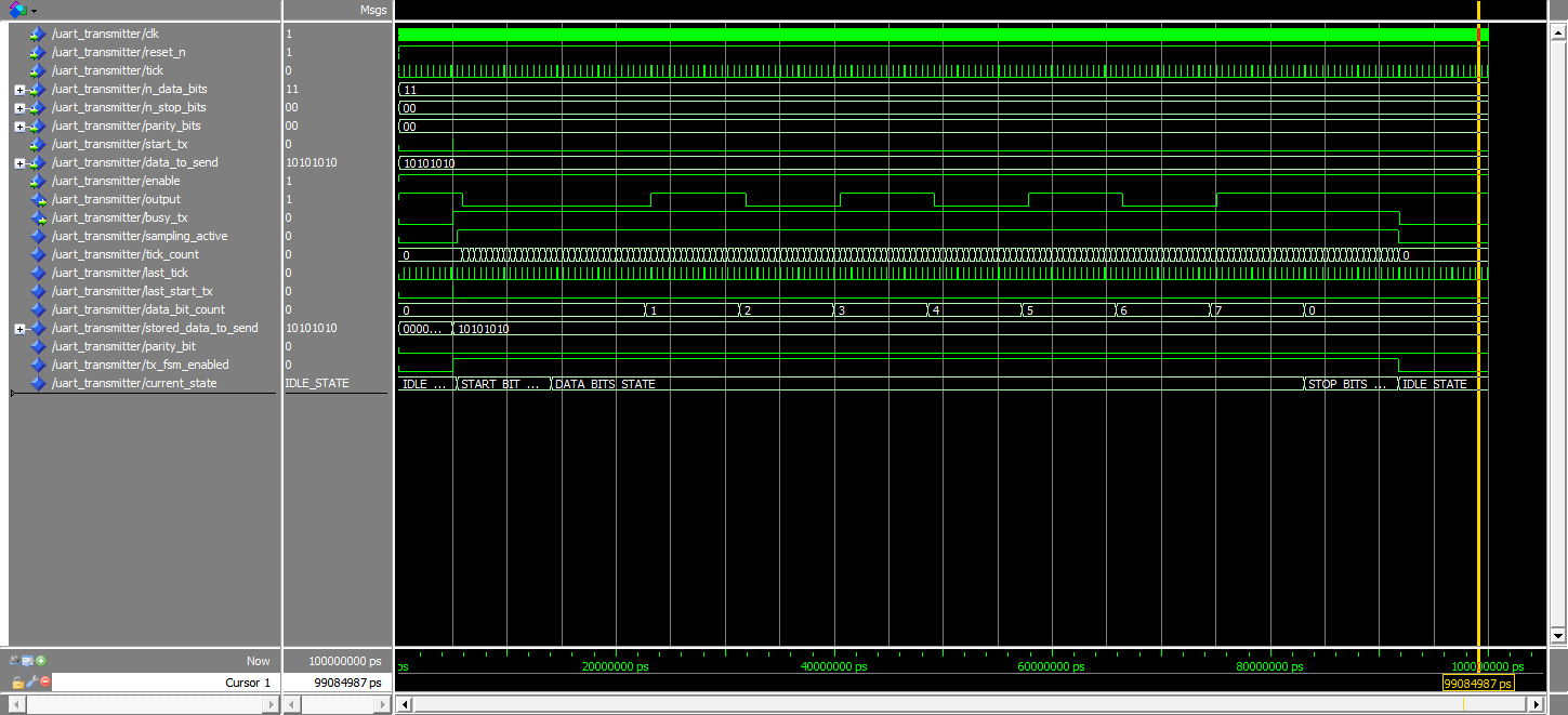
UART Transmitter Simulation
A transmission is started by setting the start_tx signal and at the same time setting data_to_send to the data which should be transmitted. This enables the FSM and data_to_send is stored temporarily inside the transmitter. At this point busy_tx is set to notify the user that the transmitter is busy and nothing will happen if the user tries to set start_tx now. Only when the transmission is done and busy_tx is reset a new transaction can be started.