RS 232 Module
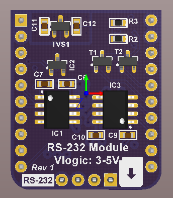
Top View
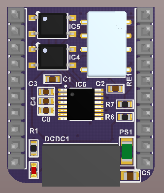
Bottom View
Schematics can be found here.
- Module ID: 5
- Fully isolated power and signals
- Outputs can be disconnected with a relay
- Two channels that can be set to TX or RX independently with CTRL pins
- IN_A: OUT_A - Outgoing data on channel A
- IN_B: IN_A - Incoming data on channel A
- IN_C: SWITCH - a HIGH signal switches the output relay ON and connects the outputs to the connector
- IN_D: ID - Used to set the module ID
- IN_E: CTRL_B - A HIGH signal sets channel B to an output and a LOW signal sets it to an input
- IN_F: CTRL_A - A HIGH signal sets channel A to an output and a LOW signal sets it to an input
- IN_G: OUT_B - Outgoing data on channel B
- IN_H: IN_B - Incoming data on channel B
- OUT_A: 5V isolated
- OUT_B: GND isolated
- OUT_C: CH_A_SWITCHED - The switched channel A pin, RS-232 compatible
- OUT_D: CH_B_SWITCHED - The switched channel B pin, RS-232 compatible
- RS-232
The board is 4 layer, 23.5x28 mm.

Mechanical Drawing