Oscar Software Framework Manual Vision Module
Go to Table of Contents.
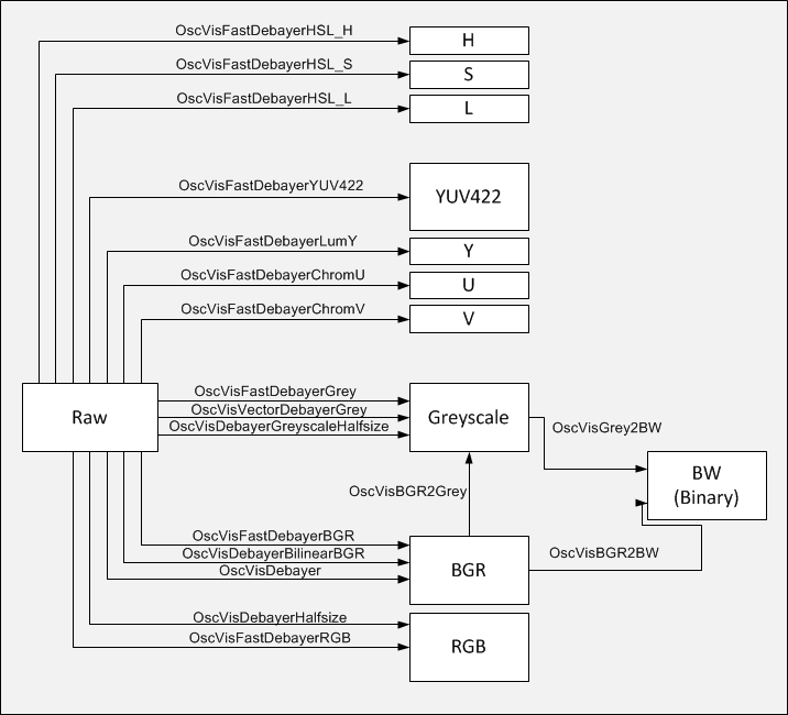
The module contains a number of functions for image processing. Currently these are mainly functions for color space conversions and debayering. Furthermore, there exist a number of functions for image filtering and binary mathematical morphology, including connected component labeling.
Not hardware resource related.
None.
Following code segment demonstrates the usage of the vis module in case for an object detection. For the sake of simplicity, error checking is neglected.
OscVisBGR2Grey(&picBGR, &picGrey); /* (2) */ OscVisFilter2D(&picGrey, &picGrey, pTempBufferHalf, &GAUSS3X3); /* (3) */ u8BrightnessThresholdValue = 128; bDetectDarkObjects = true; OscVisGrey2BW(&picGrey, &picBW, u8BrightnessThresholdValue, bDetectDarkObjects); /* (4) */ OscVisErode(&picBW, &picBW, pTempBufferHalf, &DISK8, 1); /* (5) */ OscVisDilate(&picBW, &picBW, pTempBufferHalf, &DISK2, 1); /* (6) */ OscVisLabelBinary(&picBW, ®ions); /* (7) */ OscVisGetRegionProperties(®ions); /* (8) */ OscVisDrawCentroidMarkers(&picBGR, ®ions); /* (9) */ OscVisDrawBoundingBox(&picBGR, ®ions); /* (10) */
- Convert the raw data to a BGR color image. (Note that all the OscVisFastDebayer... functions require a OSC_PICTURE struct as parameter, in which meta-data like width, height and image type are stored along with the actual image data. In this example, it is assumed that a OSC_PICTURE struct named picRaw exists. All the intermediate images in the upcoming functions are also OSC_PICTURE structs. They all are assumed to be initialized.)
- Convert the BGR color image to a greyscale image.
- Filter the greyscale image with a 3x3 Gauss filter kernel. Severel filter kernels are provided with the vis module. They are structs of type OSC_VIS_FILTER_KERNEL
- Convert the greyscale image to a black-white (BW, binary) image by brightness thresholding. It is possible to specify whether dark or bright image greyscale pixels are treated as foreground pixels.
- Perform binary mathematical morphology. Here, an erosion with a disk-shaped structuring element with a radius of 8 pixel is performed. Several structuring elements are provided with the vis module. Multiple iterations of the same operation are possible: Edit the last function parameter.
- Perform dilation with a disk-shaped structuring element with a radius of 2 pixels.
- Label the foreground blobs (=regions) in the black-white image by connected component labeling. A struct of type OSC_VIS_REGIONS is required for the output.
- Calculate area, centroid and bounding box properties of the regions.
- Visualize the centroids on the BGR color image.
- Visualize the bounding box on the BGR color image.