AliOS Things lorawanapp @VSC
EN | 中文
- Visual Studio Code (VSC) and AliOS Things IDE
- lora network(the related hardware should be connected)
- End point
- MXCHIP MK3047 *1
- Gateway
- M1301 Gateway module (GTI) *1
- Raspberry Pi *1
- M1301 Gateway module (GTI) *1
- Lora Server
- LoRa App Server: It's an open-source sever package, and you can download it by yourself.
- End point
- 5VDC/2ADC power(power supply by gateway ) *1
- J-Link *1
- micro-USB line *1
- J-Flash
- serial port terminal : here we use X-Shell
- basic knowledge of lora and LoRaWAN
- AliOS-Things
-
Set up the environment : Our IDE is based on VSC, and it's suitable for windows, mac and linux. We now use windows as an example and you can know more details in related links in github.
-
Open IDE and AliOS Things as follows :
-
Select demo and board. Here, select lorawanapp and eml3047. As shown in the following picture, you can click in the bottom highlight part and select in the above part.
-
After selecting, you can click on the
Buildbutton in the bottom work bar.You will see the related output file in "out" folder in AliOS Things after compiling.
-
Them, connect MK3047 to the computer and start programming through J-Flash :
- Create programming project
- Select "Option->Project settings"
- Select "File->open data file", and select the *.bin in the binary of folder mentioned in point 4.
- Set the initial location of flash programming as 0x08000000
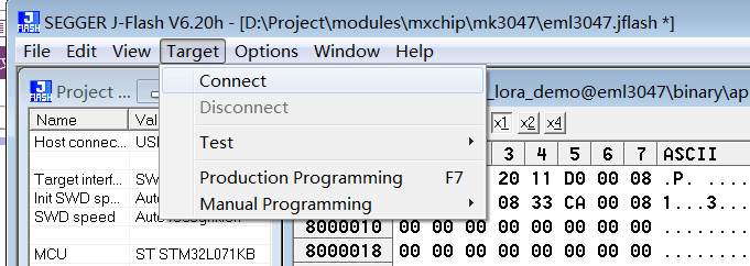
- Select "Target->Connect" to connect to the target and select "Production Programming" to start programming
-
Open X-Shell and find out related serial port. Connect to the corresponding port. Parameter is shown as below :
-
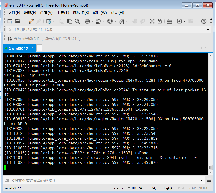
Serial port terminal will be displayed as followed after connecting. If you see the data of rssi and snr, it means that the end point has been connected to Lorawan network and started to receive gateway data.
-
The above is the programming of default code. The lorawan parameters are as follows:
Parameter Value Connecting method OTAA DevEui 31-35-37-31-50-37-7B-18(like the MAC of that board) AppEui 01-01-01-01-01-01-01-01 AppKey 2B 7E 15 16 28 AE D2 A6 AB F7 15 88 09 CF 4F 3C Class A The above four parameters can be modified in aos/example/lorawanapp/commissioning.h :


/**
 * When set to 1 the application uses the Over-the-Air activation procedure
 * When set to 0 the application uses the Personalization activation procedure
 */
#define OVER_THE_AIR_ACTIVATION                     1

/**
 * Mote device IEEE EUI (big endian)
 *
 * \remark see STATIC_DEVICE_EUI comments
 */
#define LORAWAN_DEVICE_EUI                          { 0x01, 0x01, 0x01, 0x01, 0x01, 0x01, 0x01, 0x01 }


/**
 * Application IEEE EUI (big endian)
 */
#define LORAWAN_APPLICATION_EUI                     { 0x01, 0x01, 0x01, 0x01, 0x01, 0x01, 0x01, 0x01 }

/**
 * AES encryption/decryption cipher application key
 */
#define LORAWAN_APPLICATION_KEY                     { 0x2B, 0x7E, 0x15, 0x16, 0x28, 0xAE, 0xD2, 0xA6, 0xAB, 0xF7, 0x15, 0x88, 0x09, 0xCF, 0x4F, 0x3C }
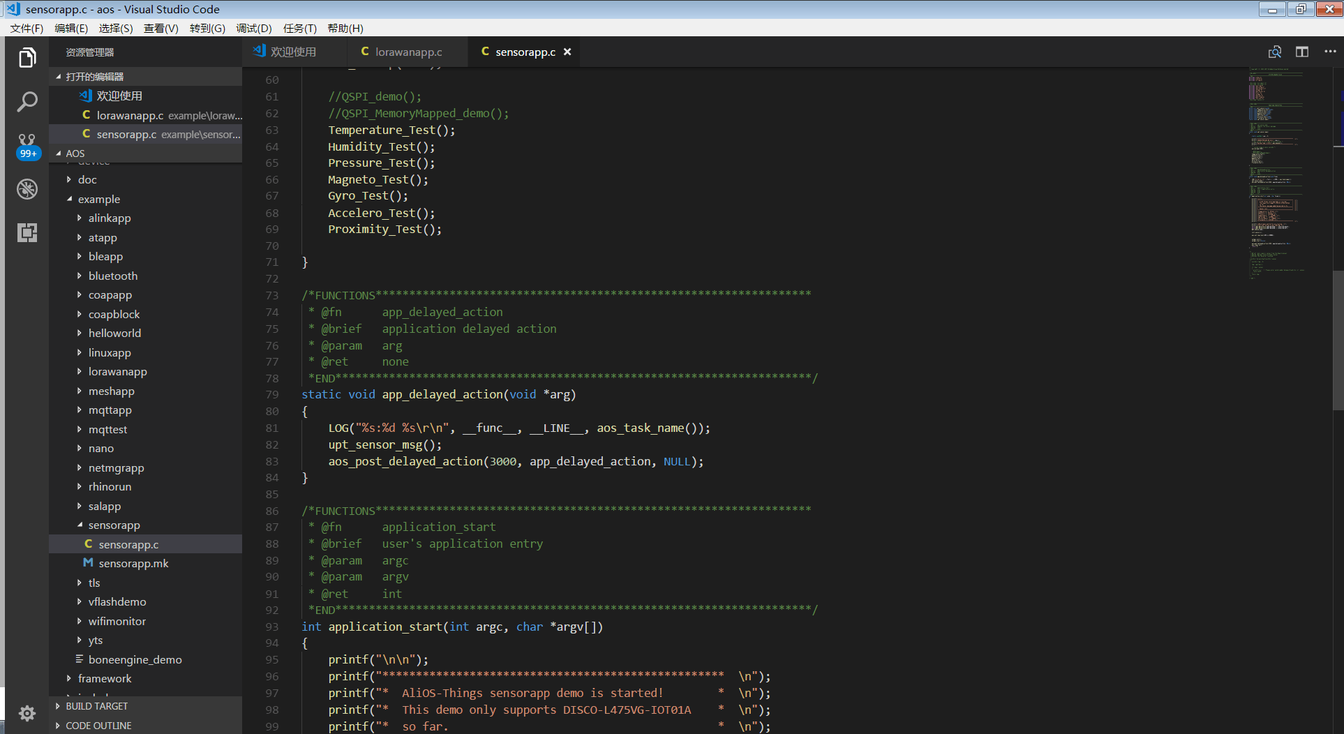
Node type can be modified in aos/example/lorawanapp/lorawanapp.c :
/**
 * Initialises the Lora Parameters
 */
static LoRaParam_t LoRaParamInit = {
    TX_ON_TIMER,
    APP_TX_DUTYCYCLE,
    CLASS_A,
    LORAWAN_ADR_ON,
    DR_0,
    LORAWAN_PUBLIC_NETWORK,
    JOINREQ_NBTRIALS
}
- Give power to gateway. ( No extra setting is needed. You only need to give it power and enable it to work. Details can refer to lorawan protocols)
-
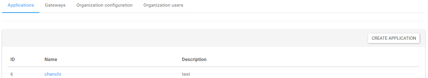
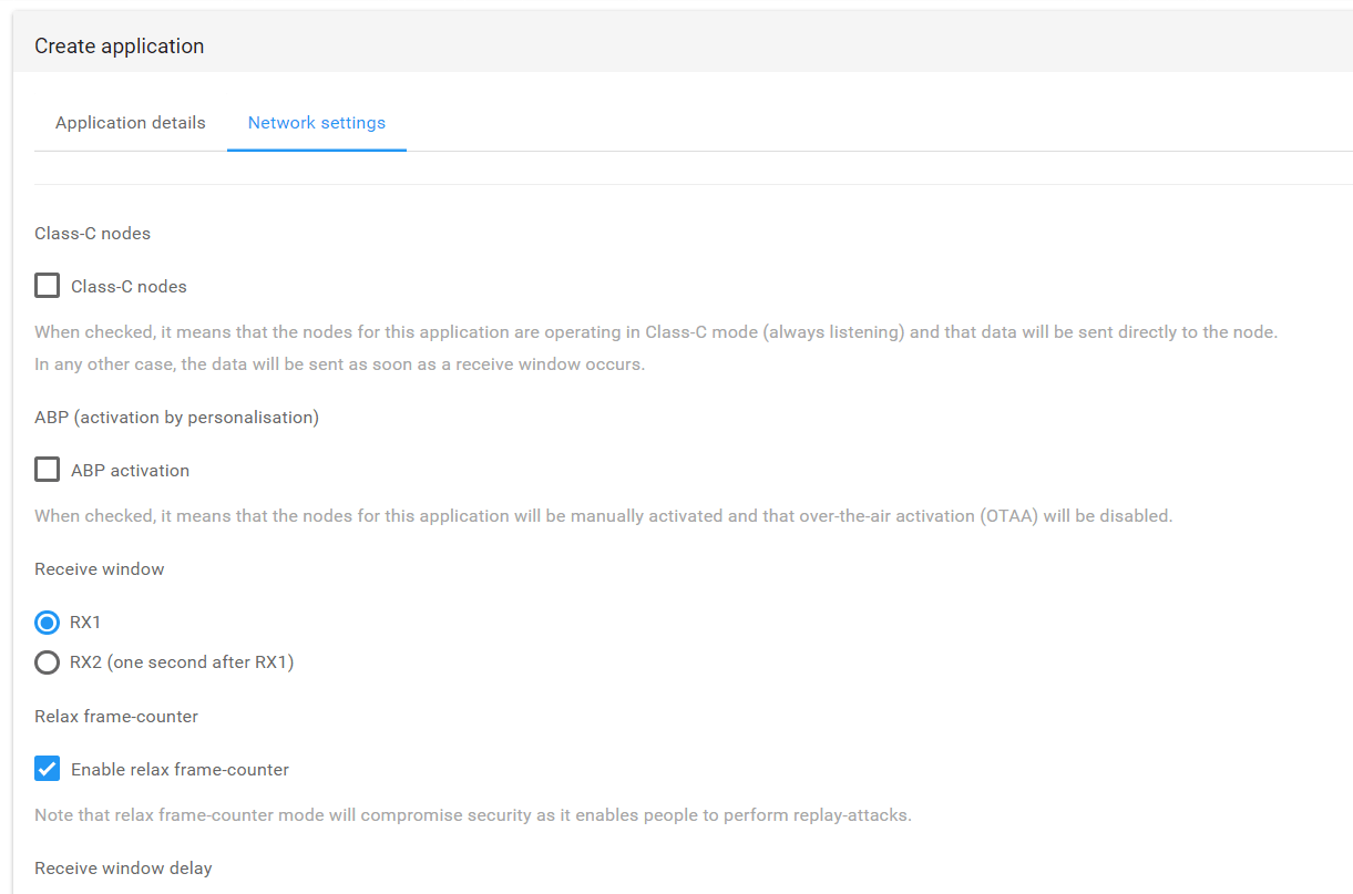
configure in server side
- Create a new project and select related parameters as followed
-
Create nodes in the application. You can fill in it according to the print information of serial terminal.
-
In the process of network connection, the terminal node will be activated and corresponding key will be generated.
-
When network connection is completed, data interaction will begin, and you will see it in raw frame logs.
-
Server side send out data
- open the api page of the server. Find out "post" in "Internal" and fill in the user name and password in "body" frame, which is "admin" and "admin" by default. Click "Try it out!" to generate Token.
-
Find out jwt field in the below response body, which is the token we need.
-
Copy the token to the blank space on the top right of the page as followed:
-
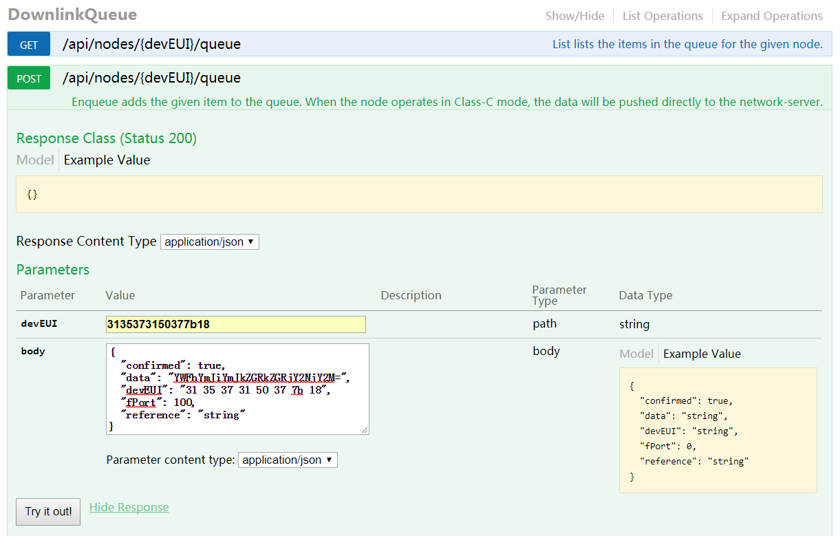
Find out "DownlinkQueue", and fill in the corresponding devEUI. Fill in the data for test and you should encode it through base64 before filling in. Set fPort as 100 and click "Try it out!" to send out data.
-
Normally, the node will receive data and print it in serial port. Till now on, the example task is completed.
If you want to try ABP, Class C(only Class A and C are supported)or other configurations, you can modify the setting of code and node mentioned above.