STM8S Value Line Gadgets
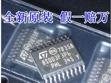
Cheap STM8S Value Line STM8S003F3P6 controllers have powerful on-chip peripherals and a generous number of port pins. Compared with other low-cost µCs the value/price ratio is excellent.
Many cheap Chinese control boards are based on low-cost STM8S µCs:
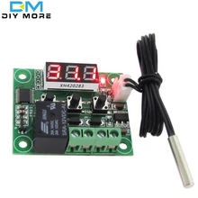
- W1209 thermostat module with relay, 3 digit 7S-LED, and 3 keys, for about $1.50
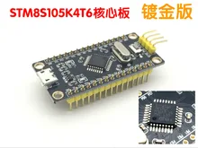
- STM8S103F3 breakout boards for about $0.75
- CN2596 DC/DC module for $1.60 use the STM8S003F3 as a voltmeter driver
- XH-M188 linear power supply with a STM8S003F3 for setting the output voltage
- ESP8266 based ESP-14 WIFI module with STM8S003F3U6 "I/O extender" for about $2.30
- many thermostat boards in the $2.00 to $4.00 range, e.g. W1219, W1401 or W1701
- many more boards, see Voltmeters, and Other Boards.
Most "cheap gadgets" are the result of "not so great" engineering. However, many boards widely available, and you can't beat the price. No matter how cheap, these boards are more reliable than the average hobby solution (e.g. an Arduino clone with "shields") even if manufacturers today often use the mostly pin compatible N76E003AT20, a MCS-51 type µC, that doesn't have the elegant ICP and IAP programming features of the STM8. The boards are very affordable even if you have to replace the µC!
STM8 eForth is like an interactive OS for STM8 µCs: a "REPL" console with interpreter and compiler, a "dictionary" of words (e.g. user programs, routines, functions, or constants), easy to use multitasking and an autostart feature. It's like an early 80s BASIC computer that runs on the µC, and it can be used as building blocks for your application. A serial terminal is used for interacting with the Forth console, but it's also possible to connect a keyboard and a display with the help of character I/O drivers.
Many boards are easy to reverse-engineer, and this Wiki presents the result. In the releases section, for some popular boards binaries are provided. The section recommended rools contains a "shopping list" to get you started.
Warning: a substitute chip for the STM8S003F3P6 made by Nuvoton, not compatible with STM8 code, now appears on many boards, e.g. on the popular W1209. The Nuvoton chip is based on MCS51 architecture, hence it's incompatible with STM8 eForth. It's advisable to specify your µC requirements prior to an order even though pictures of a board show an STM8S003F3P6 chip!
In most cases, replacing the chip with an STM8S003F3P6 is easy. In any case it's easier than designing, making and populating your own PCB!
For experimenting with STM8S003F3 peripherals a STM8S103F3 breakout board is the best point to start. STM8S003F3 and STM8S103F3 are essentially the same chip - just the specs differ.
Besides the boards described below, many other STM8S breakout boards are available. The STM8 eForth repository provides configurations that should work with most STM8S and STM8L boards.
The most common STM8S103F3P6 $0.65 boards have no crystal.

For a quick start, download the latest stm8ef-bin.x.x.x.zip, extract the MINDEV.ihx and program it to the breakout board with ST-LINK, connect a USB-TTL interface to PD5 and PD6, and start a terminal program at 9600,8,1,N. More information is available here.
The page Breakout Boards contains details.
"Access Line" breakout boards are a bit more expensive (from about $1.65). They can be used when more memory or I/O pins are required, or as a cheap alternative to the STM8S105C6T6 based STM8S Discovery board.
The board shown below has an 8MHz crystal: when using it the STM8S only runs at 50% of the rated speed. The internal 16MHz HSI oscillator can be used instead.
The page Breakout Boards contains more information.
Some of the cheapest boards are thermostat modules. Most thermostats provide a 7S-LED displays, keys, a sensor input, and a relay (some have two relays, others use MOSFETs).
SmartClima or XINHE/SINHE thermostat units or boards like the (XH-)W1209 are likely to work. The design of most thermostat boards is simple, and once the schematics is known they can be used for other control tasks.
At least the following common thermostat types are STM8 based: XH-W1209, XH-W1210, XH-W1215, XH-W1219, XH-W1301, XH-W1302, XH-W1304, XH-W1308, XH-W1313, XH-W1401, XH-W1403, XH-W1403, XH-W1411, XH-W1501, XH-W1503, XH-W1504, XH-W1505, XH-W1601, XH-W1701, XH-W1702, XH-W1711, XH-W2100, XH-W2101, XH-W3001, and XH-W3002.
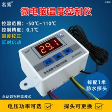
Some thermostat types have a front panel, or a plastic case (e.g. XH-W3002 thermostat with 3 LED digits,a and 2 keys, or the similar XH-W3001 thermostat with "220V" power supply).
There are also thermostat units that were designed for installation in industrial control panels, e.g. XH-W2024.
The W1209 (actually XH-W1209) is a very low cost thermostat unit, and an interesting target for hacking: for less than $1.50 it's a rather complete µC board with I/O (analog input, relay, display, keys). Other than its intended usage as a thermostat it can be applied to many simple automation, timing, or control tasks.
The page "Board W1209" contains a detailed hardware description, and programming examples.
The W1219 (XH-W1219 from SmartClima) is a low cost thermostat unit similar to the W1209 and W1401. It has an analog input, a relay, 2x3 digit 7S-LED displays (red and green), and 3 keys.
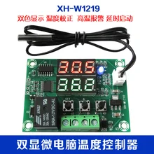
The page "Board W1219" contains more information.
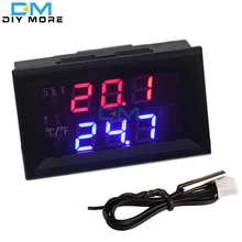
This module looks quite similar to W1219 in a nice bezel. Unfortunately mine has the nameless CPU.

The page "Board W3230" contains more information.
The W1401 (XH-W1401 from SmartClima) is a low cost thermostat unit similar to the W1209 at a slightly higher price. It has an analog input, a relay, 3x2 digit 7S-LED displays, 4 keys, and a buzzer.
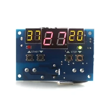
The page "Board W1401" contains more information.
The W1209WK is not fully supported. However, it has been reverse engineered, and it's maybe useful for some applications.
The page "Board W1209WK" contains more information.
The W1701 is a very basic thermostat board (no LED display, DIP switches as inputs). Unless you need a board that's a bit smaller than a W1209 (or that provides DIP switches) the W1209 is likely a better choice.
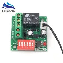
There are no plans for supporting the W1701. However, issue #23 contains the STM8S003F3 pin mapping, some Forth code for reading the DIP switches and controlling the output, and a binary file.
There are several relay I/O or just relay boards. Most of them are easy to use, some might require reverse engineering.
A "Nano PLC" marketed "Relay Board-4", or "C0135", but otherwise unbranded. It offers 4 relays (NO, NC), 4 input terminals, and an RS485 interface. At a price of less than $8.99 it's an interesting product. Of course, it also has shortcomings, e.g. the input terminals are connected to unprotected 3.3V port pins.
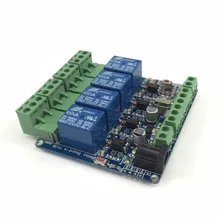
See Board C0135 for a detailed description.
The HC12 is a wireless Communication board based on the SI4463 bidirectional radio chip. HC11, a similar module, is based on the CC1101 radio chip. Other boards based on STM8S003F3P6 provide an interface to NRF24L01+ modules.
Work-in-progress for the HC12 was taken from al177/stm8ef into this repository.
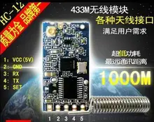
The page "Board HC12" contains more information.
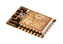
STM8S003F3 µC and ESP8266 SoC in the same package as the ESP-12. As it's not difficult to control the ESP8266 power supply from the STM8S003F3, this module should be an interesting target for creating very low power IoT devices.
The ESP-14 has the following properties:
- Independent power supply of both µC and SoC
- all STM8S003F3 µC pins broken out
- one ESP8266 SoC pin broken out
- ESP8266 SoC pre-programmed with "WIFI modem" code
- µC and SoC UART pins connected internally, but accessible on the outside
Some more info is here.
@hexagon5un published an article on building a WiFi connected IoT device with the ESP-14, MQTT, and STM8EF on Hackaday. The project sources and docs are here on GitHub.
@RigTig develops an awesome 100 cubic meter 3D printer based on a networked array of ESP-14 units. The ESP8266 runs Punyforth for network code, and the STM8S003F3P6 runs TG9541/STM8EF for the GCODE interpreter, and motor control. The code repository also includes STM8EF math routines, and a nifty upload-tool written in Python.
There are many cheap 3 or 4 digit voltmeter, some of which are STM8S003F3P6 bases. Unfortunately most of them lack a "brand" or generic "module name". If you order a "3 digit voltmeter" on the description alone, there's no way to know what you'll get. In some cases the device you receive might not have the same design as what somebody described on the Web. Also be aware that some vendors might use a popular keyword, like STM8S003, to improve their search engine rating. Once a suitable board has been identified, it's best to order the required quantity from the same seller right away.
If you're looking for STM8S based voltmeters, here is a starting point:
- Detailed description of a 3 digit voltmeter on Hackaday in the scope of the TG9541/STM8EF
- 0.36inch 4 Digit Digital Panel Voltmeter 0-33V, see Hacking a cheap voltmeter
- 3 Digit digital volt meter (search: STM8S003 LED)
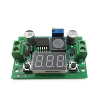
Sometimes the voltmeters are part of a different type of application, e.g. a power supply. The Page Board CN2596 shows a very attractive target.
The board XH-M188 is a cheap regulated power supply advertised as "XH-M188 numerical control voltage regulation module", and rated "0-12V 1.5A 18W".
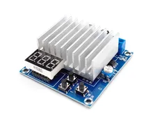
See Board XH-M188 for a detailed description.
This STM8 eForth primarily targets STM8S "Value Line", and low-end "Access Line" devices. Midrange "Access Line" STM8S105 µCs are supported, and there is a plug-in system for other STM8 devices.
Most STM8S based boards were designed for a narrow use-case, not as an embedded control development platform. As such, most often they don't have the serial interface pins broken out to headers, but a 4 pin programming interface is often available for production purposes.
The binary release contains the image SWIMCOM, which simulates a 2-wire half-duplex communications interface on PD1/SWIM.
The recommended circuit for connection to a USB RS232 "TTL" adapter is this:
STM8 device    .      .----o serial TxD "TTL"
               .      |      (e.g. "PL2303" USB serial converter)
               .     ---
               .     / \  1N4148
               .     ---
ICP header     .      |
               .      *----o serial RxD "TTL
               .      |
STM8 PD1/SWIM-->>-----*----o ST-LINK SWIM
               .
NRST----------->>----------o ST-LINK NRST
               .
GND------------>>-----*----o ST-LINK GND
               .      |
................      .----o serial GND
e4thcom fully supports STM8EF 2 wire connections, and an example picocom configuration for half-duplex communication is described here.
Judging from product descriptions many XH-Mxxx or Bxxxx labeled boards from the usual Chinese market sites are STM8S003F3P6 based. Some of them are extremely cheap, others are in the $10-$20 range but have interesting features (e.g. XH-M114, XH-M117, XH-M128, XH-M129, XH-M158, XH-M188, XH-M194, XH-M196,XH-M203, XH-M205, XH-M207, XH-M241, XH-M602, XH-M603, XH-M604 ...)
It's best if the serial port pins are easily accessible on headers, but that only applies to a small fraction of the boards. TG9541/STM8EF provides support for all boards that have at least one free GPIO (e.g. PD1/SWIM on the ICP header), and in many cases sharing the communication port with another functions is possible.
There are many other more or less cheap devices available that might be based on STM8S µCs, here are a few:
- Brushless DC (BLDC) motor controllers for below $20.00 (e.g. for e-bike motors) use STM8S103 or STM8S105 µCs. Opensource firmware exists.
- Ebike motors and displays TSZD2 motor and KT-LCD3 display use STM8S105; The displays e.g. KT-LCD3 are a serial LCD display unit.
- STM8S103 one way relay module , all µC pins available on headers
- STM8S003F3 4 Digit digital timing module
- 3 Digit digital timing module
- Motor Driver
If you apply the code to any STM8 based target, the STM8 eForth community is always happy to hear about it!
For creating a variant simply copy a board folder (e.g. CORE) to a new folder. Running make BOARD=<folderName> flash builds the code and transfers it to the target.
From STM8 eForth 2.2.24 on the binary release also contains the STM8 eForth source and the core of the Makefile. How to create a custom board support repository is explained in the DEMO folder of Modular Build.
When working on 3rd party boards it's recommended to have at least two boards: one in the original state and one for testing your new code. If you've identified a target board of general interest please open a ticket in this repository or contact the STM8 eForth Hackaday.io project.
Please keep the following in mind:
- when working on unknown boards make sure to have at least a basic understanding of the schematics and workings of the board! The author(s) of this software may have no way to help you reverse-engineering an unsupported board. Some electronics know-how is required!
- the original Flash ROM contents of most boards can't be read since it is read-protected. Once erased the original function can't be restored (your board will be useless unless you write your own code)!
- if your target board is designed to supply or control connected devices (e.g. a power supply unit) it's recommended not to assume fail-safe properties of the board (e.g. the output voltage of a power supply board might rise to the maximum without the proper software). Disconnect any connected equipment, and if possible only supply the µC with a current limiting power supply!
Other than that please share your results and have fun!
If you have the patience to wait 2 to 8 weeks "Free Shipping" from China takes, a $5 investment will get you started.
The ICP (in circuit programming) port of most boards is unpopulated, and even breakout boards are shipped with unsoldered header pins. Basic soldering skills are required (please consider getting in touch with a maker group near you for basic training), and soldering tools need to be available (I don't recommend buying a $3.00 soldering iron, but it's better than nothing).
For testing time critical routines (e.g. interrupt driven communication) a cheap logic analyzer with Sigrok is useful.