Board W1209
The W1209 thermostat module has a STM8S controller, a sensor input, keys, LED display, and a relay. Applications of the board aren't limited to temperature control: it can be reprogrammed for other embedded control tasks like timing, counting, or even ultrasonic distance measurement. At a unit price of below $1.50 it can be used for many "set and forget" applications.
Note: there have been reports of more or less compatible W1209 clones. Please refer to the identifying W1209 boards page for more information!
A GitHub project for a W1209 Data-Logging Thermostat provides an alternative firmware: it's based on STM8 eForth, and interactively programming other control applications, e.g. using level, pressure, or light sensors, is easy!

The W1209 module (also XH-W1209) from SmartClima or XINHE/SINHE) has the following features:
- STM8S003F3P6 (8K Flash, 1K RAM, 128 bytes EEPROM), 5V operation, no crystal
- ICP (In Circuit Programming) pads. PD1/SWIM shared w/ 7S-LED segment "E".
- User interface: 3 keys, and 3 digits 7S-LED display
- Relay (12V operation, NO, 5A) with red status LED
- Sensor input with a XH2.54 2p male connector and 20k pull-up to 5V
- 10k NTC temperature sensor, typically with 50 cm cable and XH2.54 2p female connector
Instead of the NTC temperature sensor other types of resistive transducers can be used (e.g. for measuring light, pressure, strain, or angle). Hardware details and schematics are discussed in technical description.
The W1209 thermostat was one of the first STM8S Value Line Gadgets supported by TG9541/stm8ef. The W1209 runs its own interactive programming system, which allows code to be compiled into RAM or Flash ROM, and tested, directly on the target!
If you're new to STM8 or to Forth, please refer to the following sections
- STM8S programming hands-on
- recommended tools for STM8
- a brief introduction to STM8 eForth Programming
A HEX file for the W1209, optimized for embedded control tasks, is part of the binary release. The default configuration provides a complete interactive Forth system with sufficient free memory for typical control applications (special configurations provide more free memory). The binary can be programmed to the W1209 board using an inexpensive ST-LINK adapter.
STM8EF v2.2.13 provides a full-duplex interface through the pushbutton pins. Alternatively, with the help of a simple hardware modificatio, the sensor header can be turned into a half-duplex serial interface.
Analog inputs can be used with the words ADC! (select a channel), and ADC@ (read a selected channel):
\ define word to read from Ain6, the sensor header
: AIN 6 ADC! ADC@ ;

\ measure and print the result
AIN . 1010 ok
Note that the converted ADC value is very noisy. It's advisable to use a moving average (e.g. the method of double low-pass filer with fixed point arithmetic and linearisation used in the W1209 data logging thermostat).
The former default W1209 Forth binary used the sensor header as a serial interface for the Forth console. An example program demonstrates switching between "analog input" and "serial communication".
If the application requires reading more than one analog input, it's possible to use the GPIO PC4/AIN2 (the + key) with a only minor board modifications.
The word OUT! puts a binary pattern to the outputs. The W1209 has just one output, the relay (but the key pins can be turned into outputs, too).
\ activate the relay
1 OUT!

\ deactivate the relay
0 OUT!The 3 digit 7S-LED display and the 3 keys of the W1209 are fully supported by STM8EF vectored I/O:
- the I/O word
E7Ssends an ASCII char to the LED pattern buffer, and on the lower level the wordP7Scan be used to display an 8bit LED pattern:
\ display 0º on the 7S-LED display (48 is ASCII for "0")
48 E7S $63 P7S- Using vectored I/O it's possible to redirect console I/O to the 7S-LED display:
' E7S 'EMIT !However, the 3 digits are just enough for showing ok (the EMIT vector can be restored with ' TX! 'EMIT !).
- On the W1209, the background task by default displays data on the 7S-LED display (
E7Sis used through vectored I/O). This makes displaying measured data very simple:
\ display the ticker value
: showtimer ( -- )
  TIM U.
;
' showtimer BG !
In a background task the ?KEY vector is assigned to ?KEYB for reading board keys in the same way as ?RX does in the foreground task for reading characters from the serial interface.
On a lower level, the word BKEY reads the board pushbuttons as a bit-field (with 'set'=1, '+'=2, and '-'=4).
?KEYB does a simple translation of the key bit-field value to the characters 'A' to 'G' (with 'set' to A, '+' to B, and '-' to D, the translation is defined by BKEYCHAR in boardcore.inc). ?KEYB does key repetition by default.
The 3 keys are mapped as follows:
| Key | ?KEYB | BKEY |
|---|---|---|
| "SET" | "A" (0x41) | 0x01 |
| "+" | "B" (0x42) | 0x02 |
| "-" | "D" (0x44) | 0x04 |
Pressing multiple keys leads to an ASCII code corresponding to the value of the bit-field (e.g. "SET" and "-" result in the code 0x45 (ASCII "E").
This section contains simple Forth code examples for the W1209. More examples can be found in STM8 eForth Programming. This Wiki contains more useful code snippets, e.g. an easy to use grid point interpolation can be used for modeling arbitrary functions, e.g. for sensor linearization.
The following program ledmon for the W1209 board is a minimal RAM monitor that runs in the background:
NVM
\ W1209 background memory monitor - keys: set:'A', +:'B', -:'D'
VARIABLE addr
: inc   ( -- )
  1 addr +! ;
: dec   ( -- )
  -1 addr +! ;
: cadr  ( -- )
  DUP 66 = IF
    inc THEN
  68 = IF dec THEN ;
: disp  ( -- )
  addr BKEY IF
    ? ELSE  @ C@ . THEN ;
: ledmon  ( -- )
  HEX ?KEY IF
    cadr ELSE
    disp THEN ;
\ start word: initialization of ledmon background task
: start   ( -- )
  128 addr !
  [ ' ledmon ] LITERAL BG ! ;
' start 'BOOT !
RAM
NVM activates IAP mode). The words that compose ledmon are then compiled to the Flash memory. The word start is the initialization code that sets addr to the initial RAM address for the monitor and starts the background task by setting BG to the address of ledmon. Finally, the address of start is used as the boot routine by storing it to the 'BOOT vector. RAM "finalizes" the dictionary in the Flash ROM so that at the next cold start the new words are known, and switches back to volatile dictionary mode. The technical background is discussed here.
The (former default) W1209 binary implements a half-duplex serial interface through the analog input. This makes using the serial interface "off-line" (i.e. either the control application, or the diagnostics) very simple.
The following small program demonstrates switching between analog input and communication interface:
\ W1209 measures U with Q12.4 LPF U = adc + U - U/16
NVM
VARIABLE U
: adc   ( -- n )
  6 ADC! ADC@ 0 ADC! ;
: lpf   ( n -- n )
  U @ DUP 16 / - + DUP U ! ;
: measure   ( -- )
  adc lpf 16 / . ;
: start   ( -- )
   0 U !
   [ ' measure ] LITERAL BG !
   BEGIN
     ?KEY IF 13 = ELSE 0 THEN
   UNTIL
   0 BG ! ;
' start 'BOOT !
RAM
The word sample reads ADC6 (and then switches to the non existent ADC0 to re-enable the serial input), wLPF is the state variable of of the LPF (a Q12.4 fractional number, i.e. fixed point arithmetics), lpf is a 1st order low-pass-filter with k=1.0625. The word measure samples the ADC, applies the LPF, scales fixed point to integer, and displays the result with U.2 (in a background task this goes to the 7S-LED display).
The initialization part in start resets the LPF state variable wLPF and then sets measure as the background task. All the foreground task has to do is checking if ASCII CR (13) appears on the serial port (which indicates that the sensor has been exchanged by a serial terminal and someone has pressed the enter key). It exits the loop, stops the background task, and drops to the Forth prompt.
Finally, the interpreted phrase ' start 'BOOT ! sets the word start as the initialization routine, and RAM stores the dictionary pointers to Flash.
For transient response test of a DC/DC converter a periodically switched load was required. The following code turns the W1209 into a simple but useful piece of lab equipment:
66 CONSTANT keyset
66 CONSTANT key+
68 CONSTANT key-

NVM
\ W1209 pulse generator relay output 50% duty cycle
\ keys "+", "-": variable frequency Tmin = 2*25ms
\ key "SET": pulse on/off

VARIABLE pulse    \ pulse time in 5ms increments
VARIABLE onoff    \ bool
: inc   ( -- )    \ increment pulse interval
  5 pulse +! ;
: dec   ( -- )    \ decrement pulse interval
  pulse -5 OVER +! @ 5 < IF
    5 pulse ! THEN ;
: toggle ( -- )   \ toggle pulse on/off
  onoff @ NOT onoff ! ;
: dokey  ( -- )   \ do key actions
    DUP key+ = IF inc THEN
    DUP key- = IF dec THEN
    keyset = IF toggle THEN ;
: task ( -- )     \ pulse background task
    pulse @ DUP . \ display pulse duration
    TIM OVER 2* MOD <
    onoff @ AND OUT!
    ?KEY IF dokey THEN ;
: start  ( -- ) \ startup routine
    100 pulse !
    0 onoff !
    [ ' task ] LITERAL BG ! ;
' start 'BOOT ! \ set startup routine
RAM COLD
The code is similar to the ledmon example, which contains an explanation of the background routine task, and the startup code start.
The binary release contains two STM8EF binaries, providing different COM-port potioms: W1209 and W1209-FD. For programming one of them to a new W1209 board follow these steps:
- connect an ST-LINK (V2) programmer
- erase the locked factory programming
- program a pre-build or a custom made binary
The ST-LINK programmer should be connected to the ICP (in circuit programming) pads next to the 7S-LED display. In many cases it's possible to connect GND and SWIM only but NRST is required for erasing the factory programming, and it's safest to power the W1209 board through the programmer.
| Programmer | W1209 |
|---|---|
| +5V | Pin 1 (square pad) |
| SWIM | Pin 2 |
| NRST | Pin 3 |
| GND | Pin 4 |
For a development board, where it's to be expected that the STM8EF image needs to be re-flashed, or where a resulting application binary needs to be read, retrofitting a 4 pin programming header is often the best option. It's also possible to use a "pogo pin" device for these operations.
A new W1209 board is likely to be locked. When unlocking it following the link above the Flash ROM contents is wiped. Note that the usually unless you have access to the original W1209 binary there is no way to undo that!
Programming the W1209 using the methods described in the links above is simple and straightforward. After Programming the 7S-LED display should show the text "4th".
The W1209 doesn't have a serial communication port but that doesn't mean that one can't have a serial console.
This is the preferred method with the W1209-FD binary in the v2.2.13.snapshot pre-release.
For connecting to a deployed board clips can be used. For a development board a fixed serial cable is a better option.
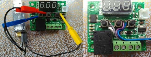
In the image above the following connections are visible:
| TTY com port | W1209-FD | clip color | wire color |
|---|---|---|---|
| GND | GND at any key | blue clip | white wire |
| TxD | key "+" (PC4, RxD) | red clip | purple wire |
| RxD | key "-" (PC5, TxD) | yellow clip | blue wire |
| - | key "set" (PC3) | - | grey wire |
Careful, some of the tactile switches become resistors with heat. The more heat, the lower the resistance. That can prevent the serial communications from taking place. Using a "pogo pin" programming cable makes soldering a pin header to the ICP pads unnecessary. When clips are used no W1209 circuit board modification is required for debugging or configuring the application software.
The analog input is on PD6, which is also the RS232 RX pin. The sensor connector cab be used as half-duplex two-wire a communication interface. The implementation uses a TIM4 interrupt for the RS232 timing. Half-duplex "communication bus" works surprisingly well for an interactive console.
Here is the simple circuit for connecting a USB-RS232 adapter to this "wired-OR" communication bus:
             .      .----o "TTL TxD"
     (5V)    .      |
       |     .     ---
       |     .     / \  1N4148
      20k    .     ---
       |     .      |
PD6----*----->>-----*----o "TTL RxD"
       |     . J1.1 NTC header
       X <- C1 removed, or replaced with max. 22nF
       |     .
       |     .
GND----*----->>----------o "TTL GND"
             . J1.2 NTC header
   W1209     .
             .
..............
A standard "TTL" interface and a diode are required. The 470nF capacitor "C1" (the one next to the sensor connector) needs to be remove from the W1209 PCB (e.g. use a soldering iron with some extra tin on the tip for better heat transfer to the pads).
Notes:
-
it's also possible to communicate through a different easily accessible GPIO, e.g. PC5 ("-" key). Please refer to issue #17
-
due to the rather poor design of the PCB there is a lot of noise on the analog input even if the C1 is in place, and averaging is always necessary. Even a 470nF capacitor doesn't help if it isn't placed close to the µC. According to the STM8S specs ADC1 has 3pF sampling capacity and a correctly placed 4.7nF would have been sufficient for 10 bit accuracy. Using the ADC without capacitor works too, but some averaging of the conversion results is necessary. If you'd intend to use the connector as a COM-port and also want to apply a capacitor to the analog input, at 9600 bit/s C1=10nF should be OK (Tbit ~ 5τ), and even 22nF should work (Tbit ~ 2τ)
-
the STM8S UART1 also has a half-duplex "bus-mode", where the same GPIO is used intermittently for Rx and Tx. Unfortunately, this mode only works with PD5 (the TX pin)
The STM8S003F3P6 pins are connected as follows:
Pin	STM	Connected to
1	PD4	7S-Dig1 (200R)
2	PD5	7S-A
3	PD6	Rx,AIN6 ((5.0V-20k)-AIN6-(NTC10k||470nF)-GND)
4	NRST	J2.3
5	PA1	7S-B
6	PA2	7S-F
7	VSS	GND
8	Vcap	C
9	VDD	+5.0V
10	PA3	Relay (1:on) 2k/10k-NPN,Relay,LED
11	PB5	7S-Dig2 (200R)
12	PB4	7S-Dig3 (200R)
13	PC3	Key "set"
14	PC4	Key "+"
15	PC5	Key "-"
16	PC6	7S-G
17	PC7	7S-C
18	PD1	7S-E / SWIM J.2
19	PD2	7S-DP
20	PD3	7S-D

The W1209 uses a 2381AS 3-digit 7S-LED display with common cathode.
Pin LED   Connected to STM
 1  Seg-E   PD1/SWIM
 2  Seg-D   PD3
 3  Seg-DP  PD2
 4  Seg-C   PC7
 5  Seg-G   PC6
 6          (no pin)
 7  Seg-B   PA1
 8  Dig3    PB4 (200R) rightmost
 9  Dig2    PB5 (200R) middle
10  Seg-F   PA2
11  Seg-A   PD5
12  Dig-1   PD4 (200R) leftmost
Someone has published the schematics:

Please note that RT 10k is the NTC, and hopefully the value for C5 in the schematics is wrong (according to the specs C5 should be between 470nF and 3.3µF).
Note: the sensor reference resistor R2 normally is 20k. Hardware variants with 5k or 10k reference resistors have been documented, and these boards require different sensor data processing when used with a standard 10k@25°C NTC. Please refer to W1209 data logging thermostat issue #17!
It's anybody's guess why the relay and the terminals are on the same side of the PCB as the display and the keys (the "set" key is almost hidden between 7S-LED and relay!). Mounting the module behind a front panel requires some tinkering (someone suggested moving the relay to the back of the PCB by drilling an extra hole). However, the W1209 board is so common that $1 laser-cut acrylic boxes are available to work around this oddity.