Breakout Boards
Breakout boards and demo board are a good way for exploring µC architectures and for testing new design ideas.
The STM8 eForth binary releases contains configurations that will work for most breakout boards with STM8S and STM8L devices with at least 8K Flash:
-
CORE,MINDEV,SWIMCOMandDOUBLECOMfor "STM8S Low Density" devices (e.g. STM8Sx03F3, STM8Sx03K3), -
STM8S001J3for "STM8S Low Density" with half-duplex interface (e.g. STM8S001J3, STM8Sx03K3), -
STM8S105K4for "STM8S Medium Density" devices (e.g. STM8S005K6, STM8S105K6) -
STM8S207RBfor "STM8S High Density" devices -
STM8L101F3for "RM0013 STM8L Low Density" devices (STM8L001 and STM8L101) -
STM8L051F3for "RM0031 STM8L Low Density" devices (e.g. STM8L050 and STM8L051) -
STM8L151K4for "STM8L Medium Density" devices (e.g. STM8L151K4)
It's easy to build other STM8 eForth configurations (e.g. serial console, I/O-support), e.g. by adding features to the CORE configuration.
Set aside about $4.00 for basic breakout board, an ST-Link V2 programmer, a "TTL serial interface", a mini breadboard, and some patch wires when ordering from Chinese suppliers. Keep in mind that budget delivery from China can take anywhere between 12 and 80 days and that there is some risk of loss. If want to play it safe, ordering from a local dealer may be worth the premium. Feel free to open a support ticket if you're not sure about how to get started, and need advice.
You can also start with one of the supported STM8S Value Line Gadgets, or with an STM8 Discovery board (which also provides an ST-LINK interface). For the serial console the serial interface of many Arduino boards, and USB interfaces for certain old mobile phones will also work (e.g. Siemens S35). In most cases some easy soldering will be necessary.
| Programmer | TTL-Serial-Interface | Breadboard | Soldering Tools |
|---|---|---|---|
 |
 |
 |
 |
- a breakout board, e.g. STM8S103F3P6
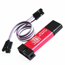
- a cheap USB ST-Link-V2 dongle ($1.80), or any STM8S/STM32 ST Discovery Board
- a USB to "TTL" RS232 dongle, e.g. a CH340 or a PL2303 clone ($0.50 to $0.80)
- a solderless breadboard, e.g. 170 or 400 points ($0.40 to $1.00), and jumper wires ($0.70 to $1.10)
- some single row headers and a soldering iron
Soldering irons for $3 with heater dial are surprisingly usable, better get one with temperature control for a bit more. It's more important that the iron has a ceramics heater element and that it's compatible with quality "HAKKO 900M" soldering tips (example).
With a breakout-board and a solderless breadboard design ideas can be quickly tested:

A ready made binary from one of the existing board support folders can be used for getting started. For flashing the binary under Linux or Windows please refer to Flashing the STM8 on the STM8S Programming page.
New in STM8 eForth 2.2.24 is the modular build: the binary release contains the STM8 eForth source code and the core of the Makefile (the STM8 eForth MODBUS, W1209 and the XY-LPWM projects all use the modular build method). The example in the modular build repository corresponds to issue #296 and to the picture above.
Finally, there is a page with nice photos in Indonesian that guides the reader through using the ST-Link dongle, flashing STM8 eForth and setting up a serial console.
For experimenting with STM8S003F3 peripherals a STM8S103F3 breakout board is a "must-have". These boards provide the following features:
- STM8S103F3P6 (8K Flash, 1K RAM, 640 bytes EEPROM), no crystal
- 4 Pin ICP interface (connects 1:1 to the ST-LINK SWIM connector)
- a reset switch
- a Micro USB connector for power supply (with 3.3V regulator, and blue or red "power LED")
- red LED on port PB5 for "blinking LED experiment"

The MINDEV binary in the binary release bundle uses the UART port for communication:
| Pin STM8S103F3P6 | Port | Connect to |
|---|---|---|
| 2 | PD5 | serial interface "TTL" RxD |
| 3 | PD6 | serial interface "TTL" TxD |
| 7 | GND | serial interface "GND" |
Other images will work too:
- the lean-and-mean CORE image
- the SWIMCOM image with half-duplex communication through STM8S003F3P6 pin17 (SWIM/PD1)
- the STM8S001J3M3 image that uses pin 2 (PD5/UART_TX) in half-duplex mode
Section Other Target-Boards explains how to use half-duplex mode.
- The internal power supply for the STM8S103F3P6 is 3.3V. If your application requires a 5V power supply, short-circuit the linear regulator by connecting pins 8 (5V) 9 (3.3V)
- when using the 5V power supply of an STLINK-V2 dongle, the 3.3 V regulator on the backside of the board will overheat unless you short-circuit the linear regulator!
- for battery powered devices it might be necessary to remove the 3.3V regulator and the power LED
- the LED at PB5 might have some effect on the I2C interface (ports PB4 and PB5)
The MINDEV binary maps bit0 of the OUT! word to the LED on PB5. A simply "blinky" for the console might look like this:
\ Blinky using the background task

: blinky
   TIM $40 AND 0= OUT!
   ;

' blinky BG !

\ type "0 BG !" to stop the task
Please refer to STM8 eForth Programming and to STM8 eForth Background Task for your next steps. For interactive programming e4thcom is recommended but any "dumb terminal" at "9600/N/8/1" will work.
To build STM8 eForth for this target run make BOARD=MINDEV flash.
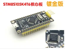
STM8Sx05 Medium Density devices provide substantially more memory and, depending on the package, more GPIOs than Low Density STM8Sx03 devices. Breakout boards with a STM8S105K4T6, available from about $2.10, can be used used as a low-cost alternative to the STM8S Discovery board (STM8S105C6T6).
The board shown below has the following features:
- STM8S105K4T6 (16K .. 32K Flash, 2K RAM, 1K EEPROM)
- 8MHz crystal (or 16MHz HSI)
- 4 Pin SWIM target interface (same pin-out as the ST-LINK SWIM connector)
- serial interface via
PD5andPD6 - blue LED on
PE5(low active, mapped to bit0 ofOUT!) [Discovery board PD0][#STM8S105K4T6 Discovery Board] - reset switch
- Micro USB connector for power supply (with 3.3V regulator, red "power LED")
Note that 16K STM8S105 devices usually have full 32K Flash memory. If you use the extra memory the caveat is that there are no guarantees.
@barewires wrote about his experience with STM8EF on a similar STM8S105K4 breakout-board here.
The STM8S105K4 binary in the binary release bundle uses the UART port for communication:
| Pin STM8S105K4 | Port | Fn | Connect to |
|---|---|---|---|
| 13 | PD5 | TX | serial interface "TTL" RxD |
| 14 | PD6 | RX | serial interface "TTL" TxD |
| 1 | GND | serial interface "GND" |
For building STM8 eForth for this target run make BOARD=STM8S105K4.
The STM8S Discovery board (manual) used to be the original STM8 target.
The board has the following features:
- STM8S105C6T6 (32K Flash, 2K RAM, 1K EEPROM)
- 16MHz crystal (or 16MHz HSI)
- STLINK built in, with 4 Pin SWIM target interface
- serial interface via
PD5andPD6 - blue LED on
PD0(low active, mapped to bit0 ofOUT!) - reset switch
- Micro USB connector for power supply (with 3.3V regulator, red "power LED")
| Port | Fn | Connect to | Pin STM8S105C6 | Discovery Bd |
|---|---|---|---|---|
| PD5 | TX | serial interface "TTL" RxD | 46 | CN4-10 |
| PD6 | RX | serial interface "TTL" TxD | 47 | CN4-11 |
If you power externally (eg. from the USB-Serial adaptor), not the usb on the discovery STLink, then after programming, remove links SB1,SB2 next to SWIM connector.
The STM8105K4T6 Breakout board binary uses PE5 as the LED output - the OUT! can be changed easily:
    1 $5011 0 B!   \  PD0 is output in DDR
    0 $500F 0 B!   \ led ON (low)
    1 $500F 0 B!   \ led off
Redefine OUT! for Simple Demo
: OUT! 1 $5011 0 B! 0= NEGATE $500F 0 B! ; \\redefine OUT!For building STM8 eForth for this target run make BOARD=STM8S105K4.
A low cost (sometimes below $3.00) "STM8S207RBT6 Development Board" is available on the usual Chinese retail sites. STM8S207RBT6 is a "High-Density STM8S Performance Line" device with 128K Flash and a rich set of peripherals. The device has 6K RAM, six times as much as the RAM in an STM8S003F3, and this is plenty for STM8 eForth applications.
Since the STM8 eForth core uses 16bit addressing only the lower 32K Flash memory are directly accessible by Forth. By building extensions with "extended addressing" it's possible to use the 96K Flash memory for storing data (or for code with CALLF and JUMPF or interrupt routines).

The board has the following features:
- STM8S207RBT6 (32K+96K Flash, 6K RAM, 2K EEPROM)
- Mini USB connector for power supply (with 3.3V regulator, red "power LED")
- Reset switch and 4 Pin ICP header (SWIM, NRST)
- 16MHz HSI or optional crystal (up to 24MHz)
The STM8S207RB binary from the Github Releases page works right away.
The STM8S207/208 provides two UARTS. As of release 2.2.23 only UART1 is supported and used for the console:
| Pin STM8S207F3P6 | Port | Connect to |
|---|---|---|
| 10 | PA4 UART1_RX | PC: serial interface "TTL" TxD |
| 11 | PA5 UART1_TX | PC: serial interface "TTL" RxD |
From release 2.2.24 on the 2nd UART (named UART3, the one with basic features) can be used for the console (refer to issue #292 and issue #302).
One of the UARTs can be used for protocols like MODBUS and up to 3 serial connections can be used by using the simulated COM port for the console.
Using standard TSSOP breakout PCBs it's fairly simple to make plain STM8S003F3 boards (e.g. for experimenting with battery operation and power saving modes). At quantities of 10, a breakout board can be made with parts less than $0.60 ($0.35 at the time of writing).
If possible use 1µF and 100nF in a 0603 package, not 0805 like in the photo:

The pads on the 1.27mm TSOP side can be cut in the middle, and used as pads for soldering the capacitors. Pin 8 can be removed from the pin header to prevent short-circuiting the internal supply voltage of the µC core (Vcap).
| Pin TSOP | Pin STM8S003F3P6 | circuit | component | note |
|---|---|---|---|---|
| 17 | 4 | NRST - VSS | 100nF 0603 | 0805 in photo |
| 14 | 7 | VSS | thin wire | |
| 13 | 8 | VCAP - VSS | 1µF 0603 | |
| 12 | 9 | VDD - VSS | 100nF 0603 | 0805 in photo |
For the units in the photo the following parts were used (cost estimate Jan/2020):
| # | Component | lot of | $/piece |
|---|---|---|---|
| 1 | STM8S003F3P6 | 10 | 0.16 |
| 1 | PCB TSSOP20 | 10 | 0.10 |
| 2 | 100nF ceramics capacitor 0603 | 100 | 0.02 |
| 1 | 1uF ceramics capacitor 0603 | 100 | 0.02 |
| 0.5 | 40 pin 2.54mm header | 10 | 0.03 |
If, as recommended, pin 8 of the pin header row is extracted, a 0603 or 0805 1uF capacitor can be soldered on the component side of a standard TSSOP20 breakout PCB:

On the backside a 1008 (2.5mm x 2.0mm) 100nF capacitor just finds a space on the SOIC20 pads on the backside. When soldered between pins 7 and 9 no cutting pads or adding wires is needed. 1008 capacitors are rare today, but it's also possible to cut the pad of pin8 to use a smaller package. It's also possible to use a small "through hole" ceramics capacitor to the pads, or to the pins on the components side.

This gives the following BOM (cost estimate Jan/2020):
| # | Component | lot of | $/piece |
|---|---|---|---|
| 1 | STM8S003F3P6 | 10 | 0.16 |
| 1 | PCB TSSOP20 | 10 | 0.10 |
| 1 | any 100nF ceramics capacitor | 100 | 0.01 |
| 1 | 1uF ceramics capacitor 0603 or 0805 | 100 | 0.02 |
| 0.5 | 40 pin 2.54mm header | 10 | 0.03 |
No 100nF capacitor was connected to NRST since the STM8S core doesn't need it. In high noise environments using one might be necessary.
To program the MINDEV binary in the binary release bundle with an ST-LINK/V2 interface use the following pins:
| Pin STM8S003F3P6 | Port | Connect to |
|---|---|---|
| 4 | NRST | ST-LINK/V2 NRST |
| 7 | VSS | ST-LINK/V2 GND or 0V |
| 9 | VDD | ST-LINK/V2 5V or 2.9V to 5.5V |
| 18 | PD1/SWIM | ST-LINK/V2 SWIM |
The MINDEV binary uses the UART port for communication
| Pin STM8S003F3P6 | Port | Connect to |
|---|---|---|
| 2 | PD5 | serial interface "TTL" RxD |
| 3 | PD6 | serial interface "TTL" TxD |
| 7 | GND | serial interface "GND" |
Custom STM8 eForth board configurations can use any GPIO (or any two GPIOs on the same GPIO group) as a serial interface.
The STM8S001J3M3 is the latest member of the STM8S low density family. As described here it behaves very much like an STM8S903x3 chip with 1 to 4 GPIOs bonded to the same pin. For testing and development it's possible to use another STM8S Low Densty device (e.g. an STM8S903K3 if you need the extra features) and "construct" an STM8S001J3 by connecting the ports on a breadboard.
Out of 8 pins, 3 are used for the power supply (Vss, Vdd, and Vcap, and since NRST was sacrificed, 5 pins are connected to GPIOs. Unfortunately, ST decided to bond PD1 to PIN8, together with PD3, PD5 and PC6. If your application configures any of those to "output" programming the chip through PD1/SWIM is no longer possible.
ST provided a reference design in the form of a small breakout board.
One of the PCBs, and two STM8S001J3M3 controllers were provided for testing. Populating the breakout board is simple (2 pcs 1µF 0603 and 1 pcs 100nF 0603 are required):

However, it's also possible to use a standard SO8N to 8pin DIP converter PCB for experimenting with the STM8S001J3M3:

In order to protect the chip from short circuit, pin3 was removed from the header, and a 1µF capacitor was soldered beween the free pad of pin3 (Vcap) and pin2 (Vss). A 100nF 0603 capacitor was soldered between a copper trace to Vdd (pin4) and the SO8N pad of pin2 (Vss).
It's possible to use the STM8S001J3M3 with the CORE or the MINDEV binary, but that's not recommended: as soon as pin8 operates as UART1_TX it's no longer possible to access PD1/SWIM for programming the chip.
Although in STM8 eForth it's possible to disable the UART through the console and thus regain access to PD1/SWIM the STM8S001J3.ihx binary release which uses UART1_TX in bi-directional half-duplex mode (2-wire mode) is safer option (this binary also works with other STM8S Low Density devices).
With the recommended 2-wire communication circuit and a good serial interface adapter, e.g. PL2303 or CH340 serial without a serial resistor in TX, this provides normal console operation , e.g. with Picocom, or e4thcom.
| Pin STM8S001J3M3 | Port | Connect to |
|---|---|---|
| 2 | GND | serial interface "GND" |
| 8 | PD1,PD5 | SWIM, serial interface "TTL" RxD/TxD |
STM8 device    .      .----o serial TxD "TTL"
               .      |      (e.g. "CH340 USB TTL)
               .     ---
               .     / \  1N4148
               .     ---
STM8S001J3M3   .      |
Pin8 UART1-TX ->>-----*----o serial RxD "TTL"
               .
GND------------>>----------o serial GND
               .
................
It's also possible to remap UART1_TX to pad5 PA3, e.g. by using the OPT! word in the library. Note that this also maps UART1_RX to the hidden GPIO PF4. This limits the console UART options to half-duplex (e.g. using the STM8S001J3 binary).
Mapping can be done by setting the option bytes with STM8FLASH or from within Forth (e.g. by the application binary):
\ alternative function remapping STM8S001J3 "PA3 = UART_TX"

\ e4thcom directives instead of manual look-up in mcu and lib folders

\res MCU: STM8S103
\res export OPT2
#require OPT!

: OptPA3TX ( -- )   \  alternative
   OPT2 C@ $03 OR OPT2 OPT!
   ;
With the STM8S001J3binary, executing OptPA3TX leads to the following alternative pin mapping:
| Pin STM8S001J3M3 | Port | Connect to |
|---|---|---|
| 2 | GND | serial interface "GND" |
| 5 | PA3, PB5 | [UART1_TX] serial interface RxD/TxD |
Cheap breakout boards like the one below are a bit more difficult to solder, especially when the solder mask is poor.

It's advisable to first solder the STM8 chip, then VDD and VSS wires in the backside (e.g. fine enamelled copper wire the backside through-hole or tacked to the spare 0.8mm pitch pads), then pin headers together with 0603 caps). The process is quite time consuming but at least it can be used as a soldering practice.