TTL Data Diode (perfboard)
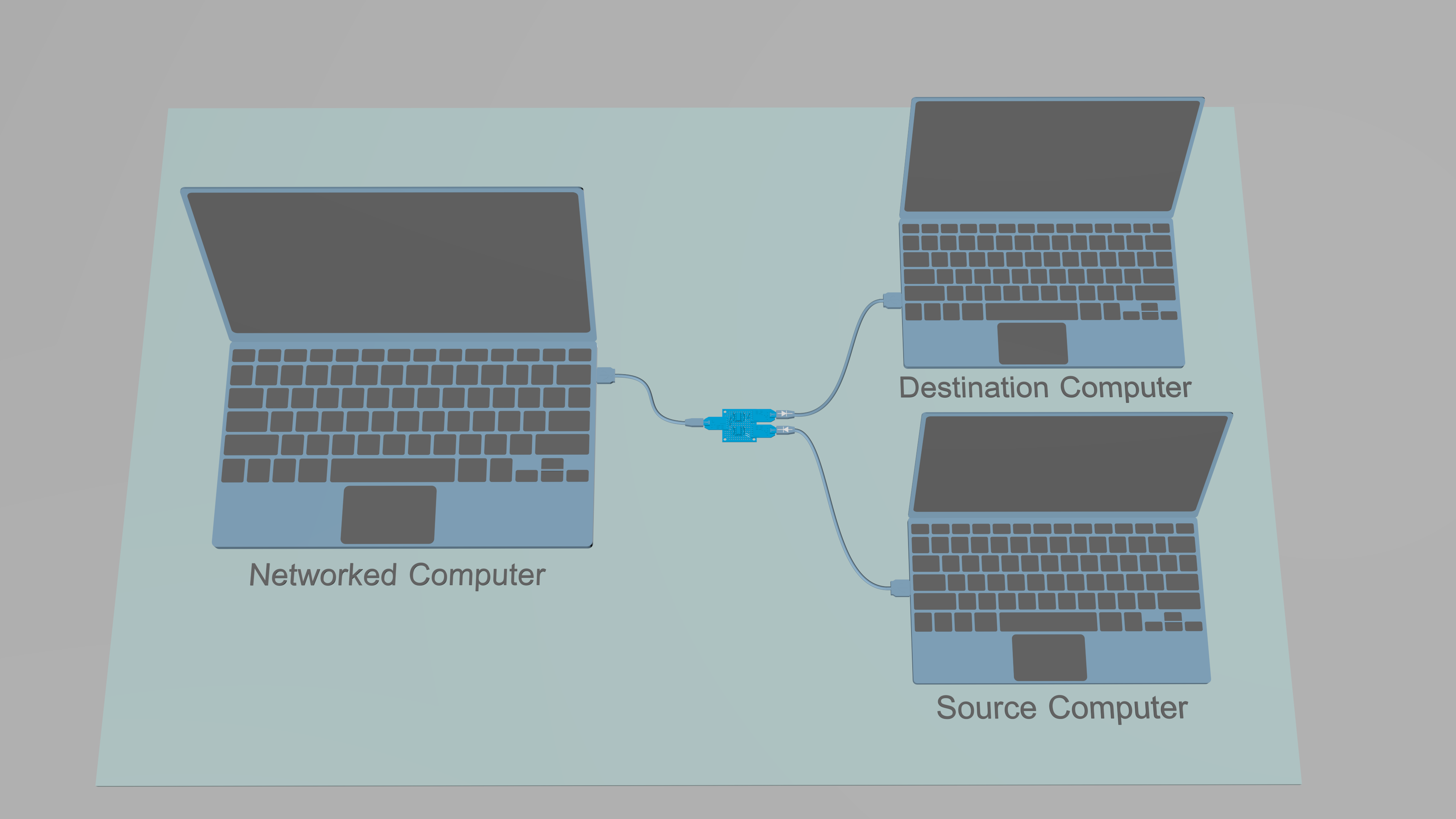
The hardware data diode is a device that allows transfer of data from one computer to another, while physically blocking transfer of data to the opposite direction. The data diode blocks all covert return channels of the link in question, even in the case where the serial interfaces (and their connected pins) are compromised, and re-programmed to send and receive data in the opposite direction.
The design of the data diode and this document are based on USB-TTL-USB Data Diode (version 16.10.a) by pseudonym Sancho_P. The design is modified and used under GNU FDL v1.3.
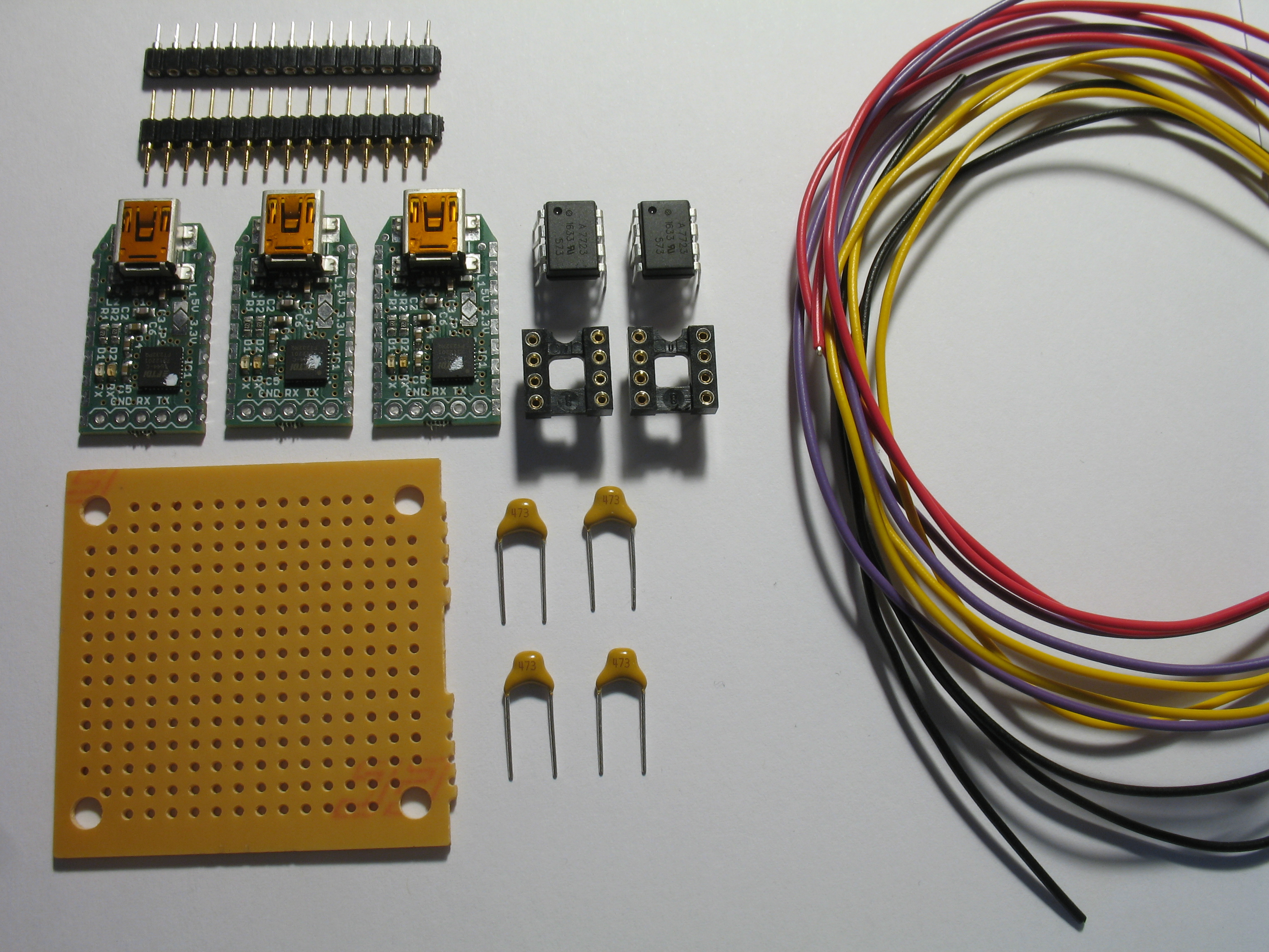
| PCS | Item |
|---|---|
| 1 | Perfboard |
| 3 | 5x1 male header (2.54mm) |
| 3 | 5x1 female header (2.54mm) |
| 2 | DIP8 socket |
| 2 | HCPL-7723 optocoupler |
| 4 | 0.01-0.1μF capacitor |
| 9 | male-to-male jump wiring |
| 3 | TTL-232R-5V USB-to-TTL adapter |
| 3 | USB 2.0 A - Mini-B cable |
| jump wiring |
As the original TTL-adapter is no longer available, the instructions below are informative only. Please refer to the schematics of the TTL-adapter to see how to connect the male-to-male jump wiring between the data diode and the TTL adapter.
As optocoupler is an integrated circuit the internal functionality of which is hard to audit, to avoid interdiction by nation states, the user should avoid buying the component online.
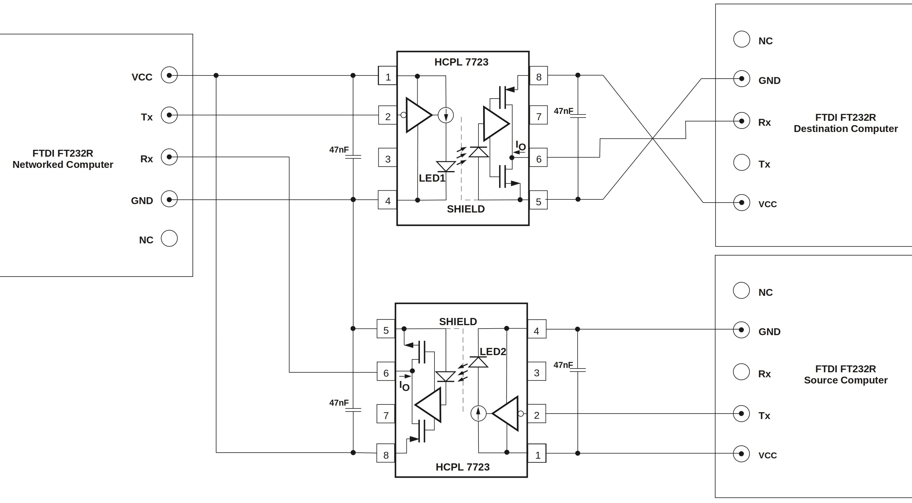
The circuit diagram for the data diode is as follows
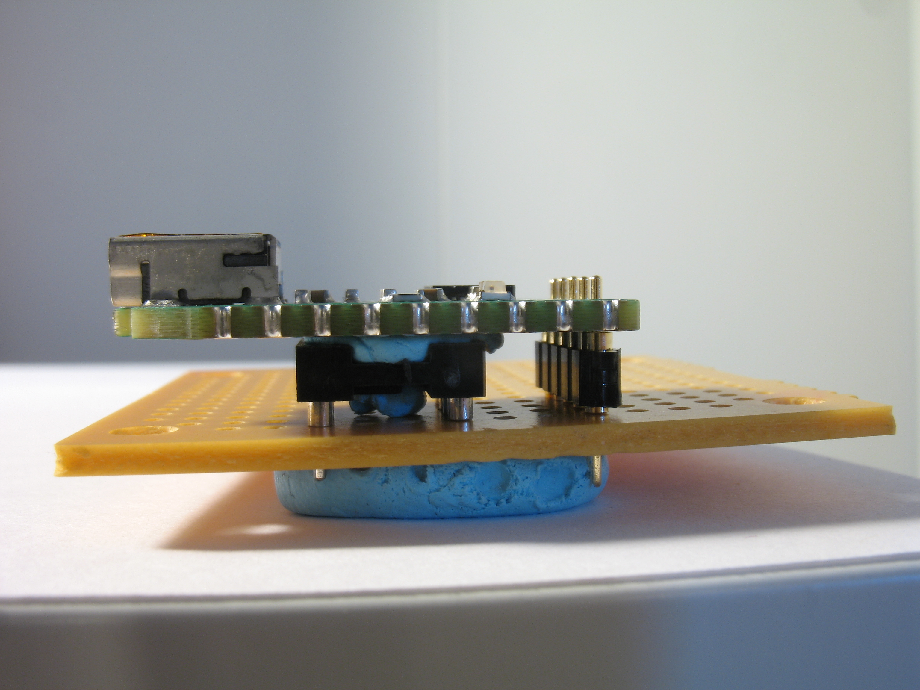
Start by cutting the male header strip into three pieces with five contact points each. Solder one male header strip to each USB-to-TTL adapter. You can use the DIP8 sockets and the perfboard to support the adapter when soldering. Blu-tack is helpful as a temporary adhesive but becomes slightly difficult to remove if it gets hot during soldering.
After soldering the headers, solder the voltage selector of each FT232R to the 5V setting. Pay attention to the picture below to see which sections the solder covers. Be careful not to bridge the V-shaped gap between the 3.3V source (pointed in red) with the center lead. Doing so will fry at least the TTL adapter once it's powered on.
Ensure the width of the capacitor leads is four pins. Use needle nose pliers to bend the leads if necessary.
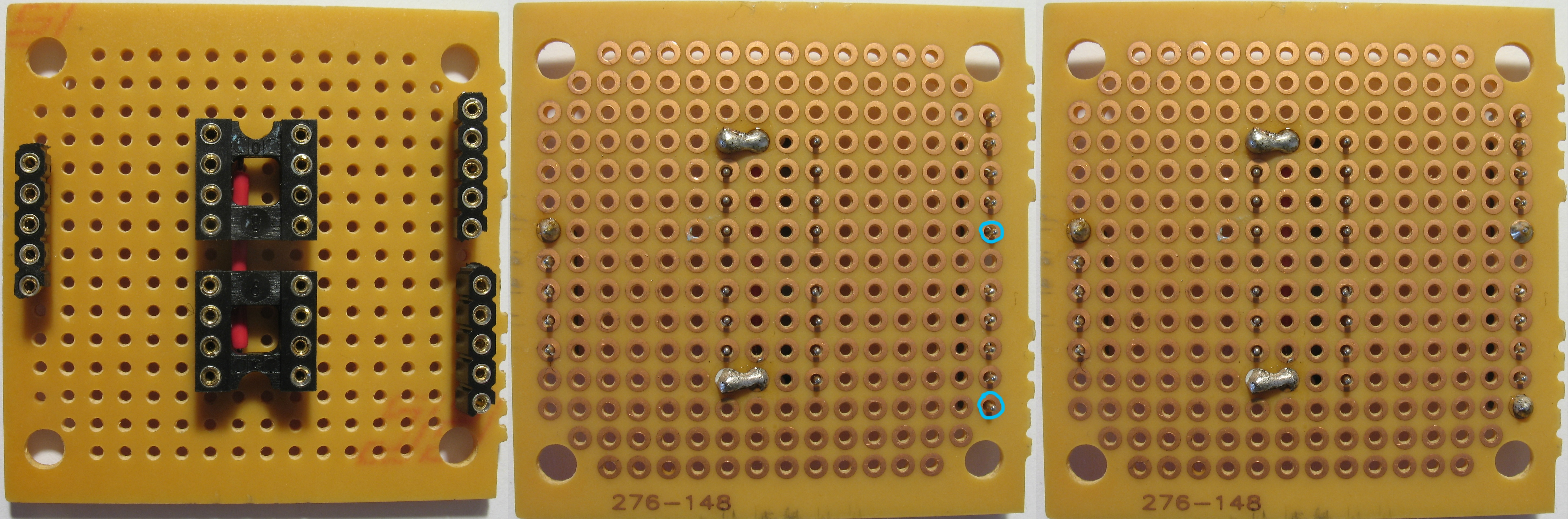
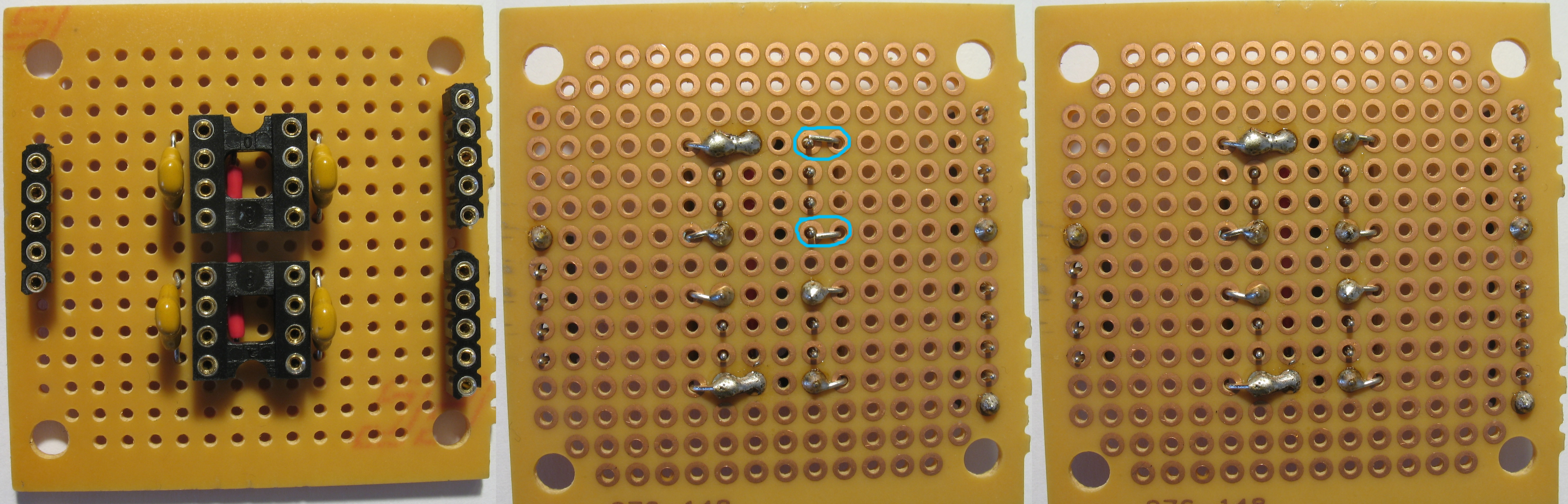
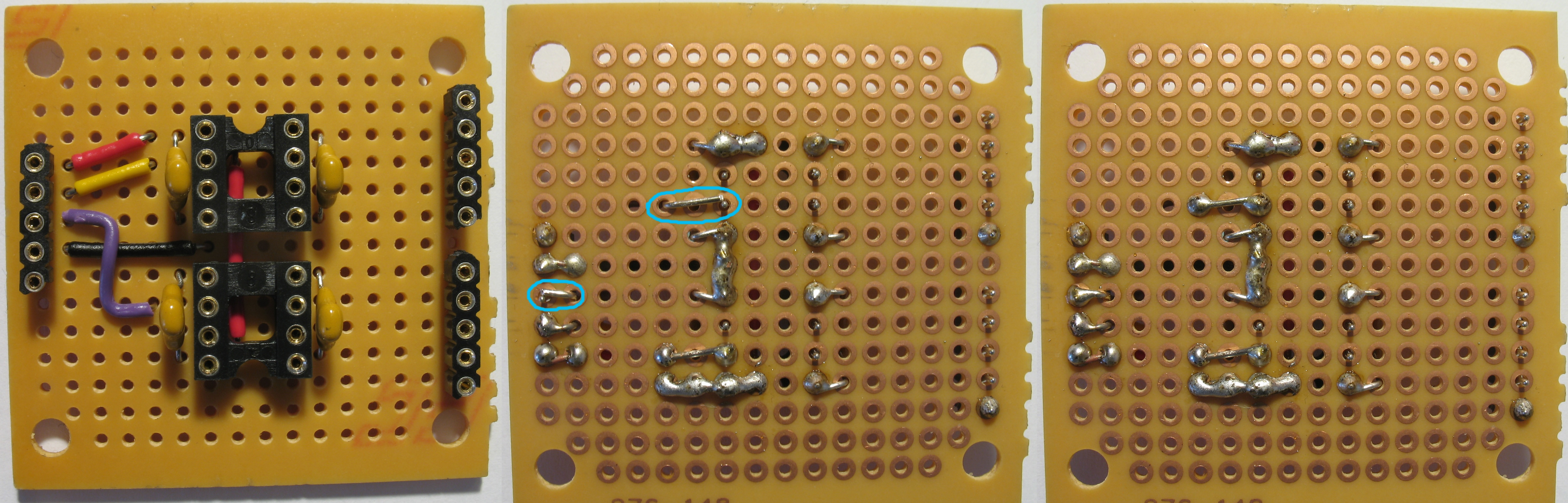
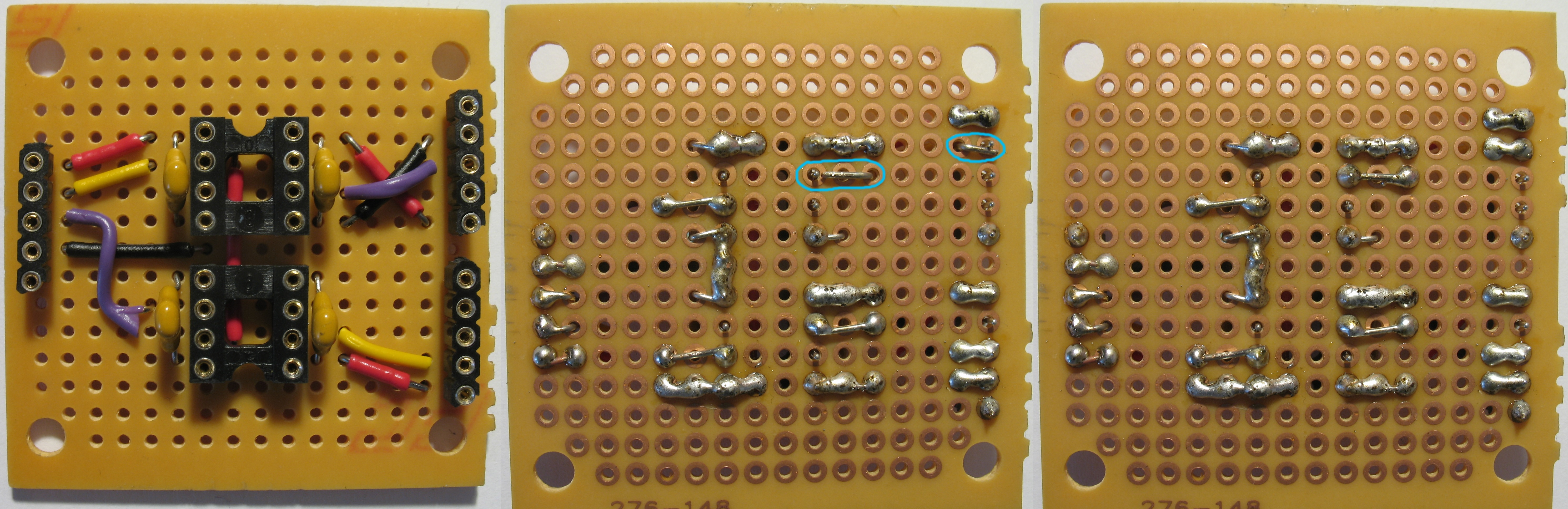
Start the assembly by placing a jump-wire on the perfboard. Place the DIP8 sockets as depicted so that the jump wire goes under it. Pay attention to the orientation of the notches in the sockets: The notches should point in opposite directions to act as a guide for optocoupler orientation later. Measuring and cutting the jump wiring takes a surprising amount of time. Use this handy guide if necessary. You can also buy ready-made kits. Note that the jump wire insulation might not be heat resistant.
Solder the jump wire to pin 1 of upper DIP8 socket and pin 8 of lower DIP8 socket.
Cut the female header strip into three pieces with five contact points each. Solder one of the pieces to the perfboard from the fifth pin that will not be soldered to anything else.
Solder the two remaining female header strips on the opposite side of the perfboard from the pins that will not be soldered to anything else.
Solder the capacitors one by one to the perfboard:
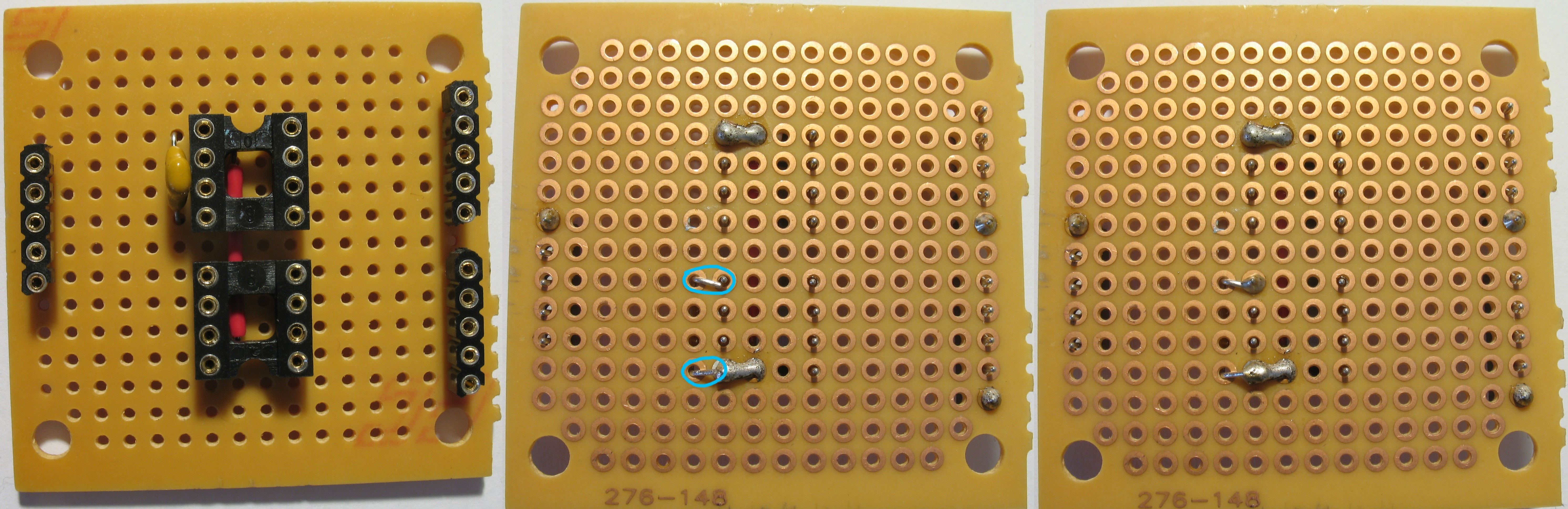
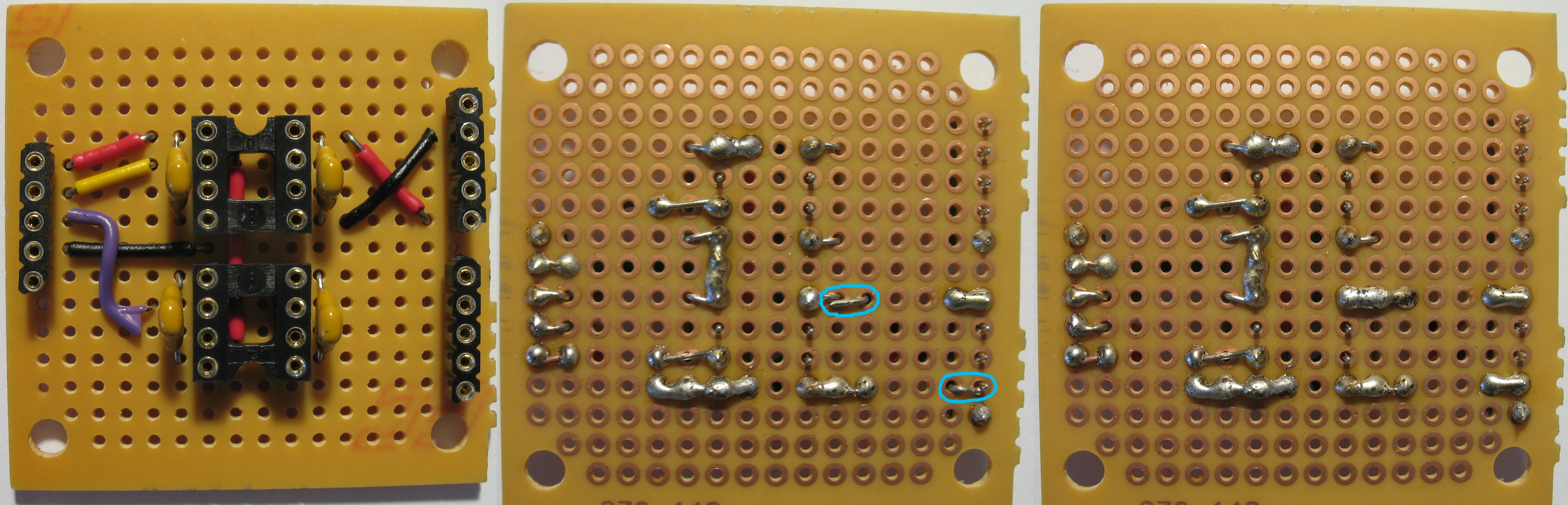
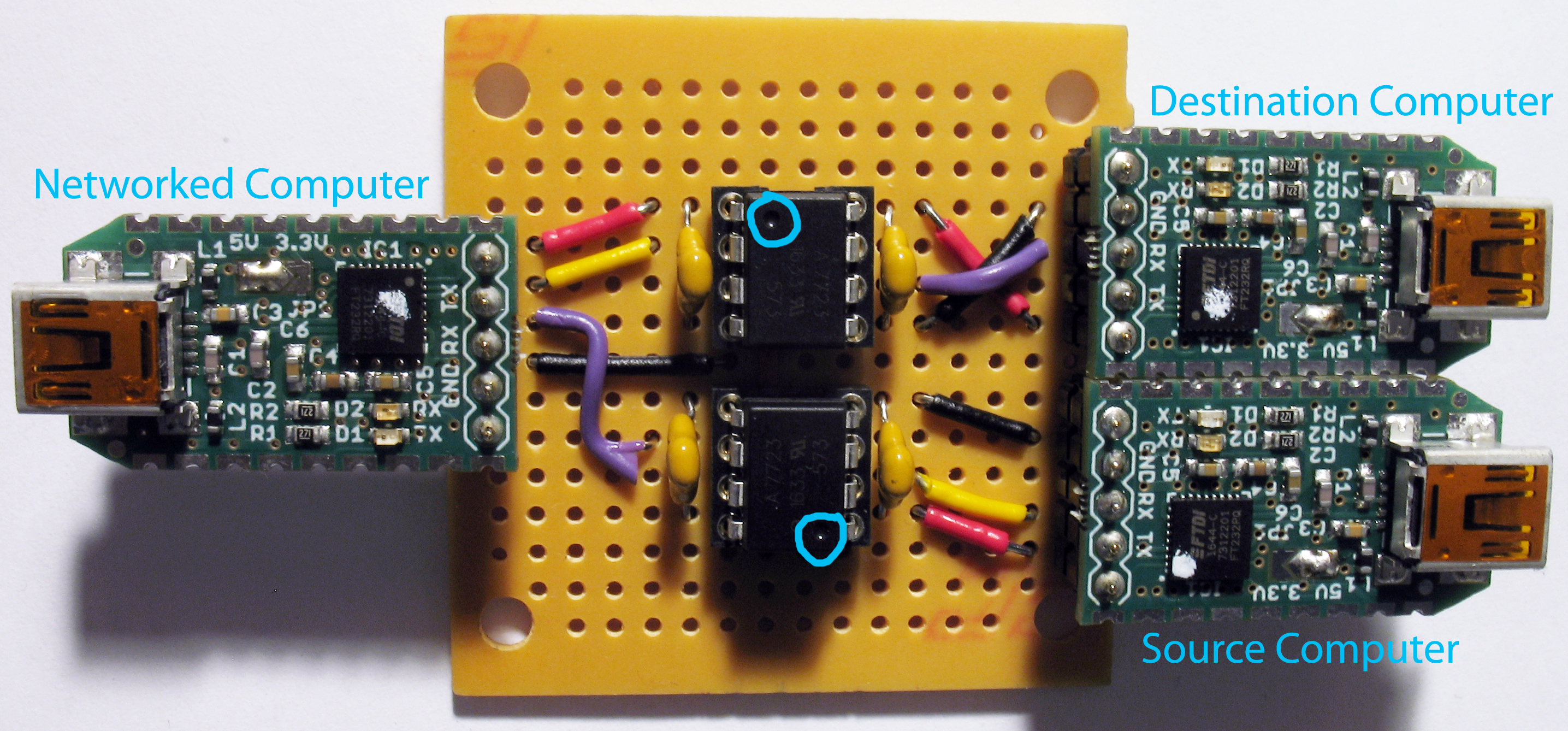
Solder the 5V VCC wire between the Networked Computer side female header strip and the lead of the nearest capacitor so that current can flow to pin 1 of the upper DIP8 socket (and using the previous jump wire, to pin 8 of th elower DIP8 socket).
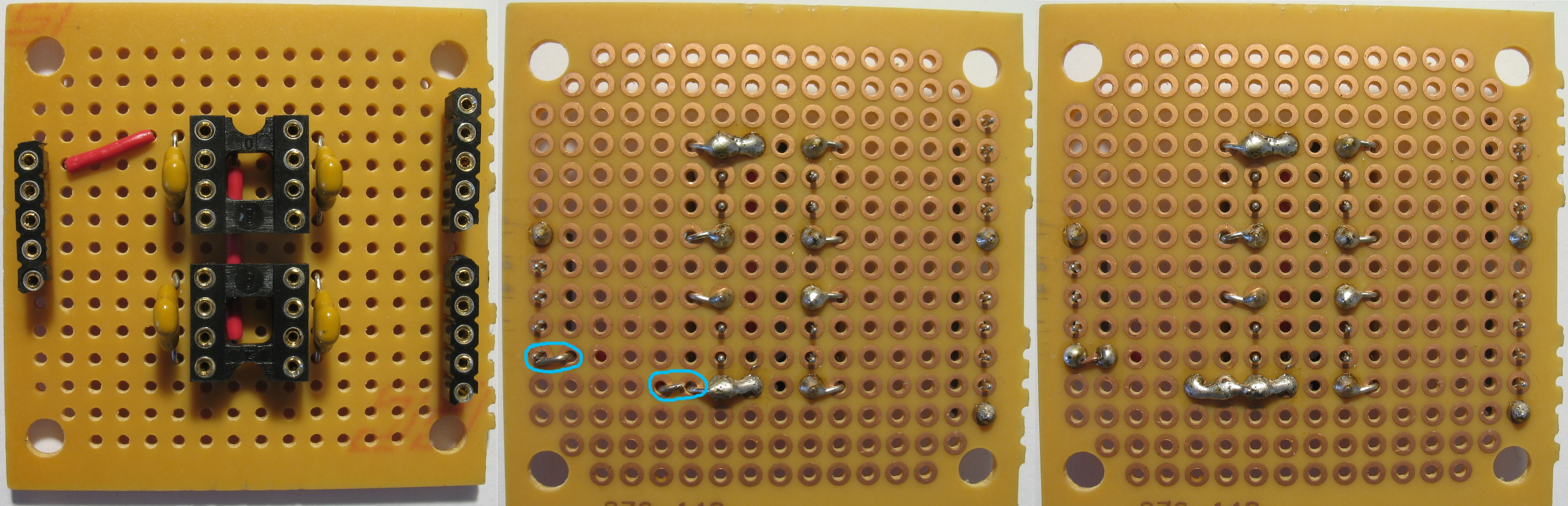
Solder the ground wire between the Networked Computer side female header strip and the hole between the DIP8 sockets. The placement makes it easy to bridge pin 4 of the upper DIP8 socket and pin 5 of the lower DIP8 socket to the Networked Computer side ground.
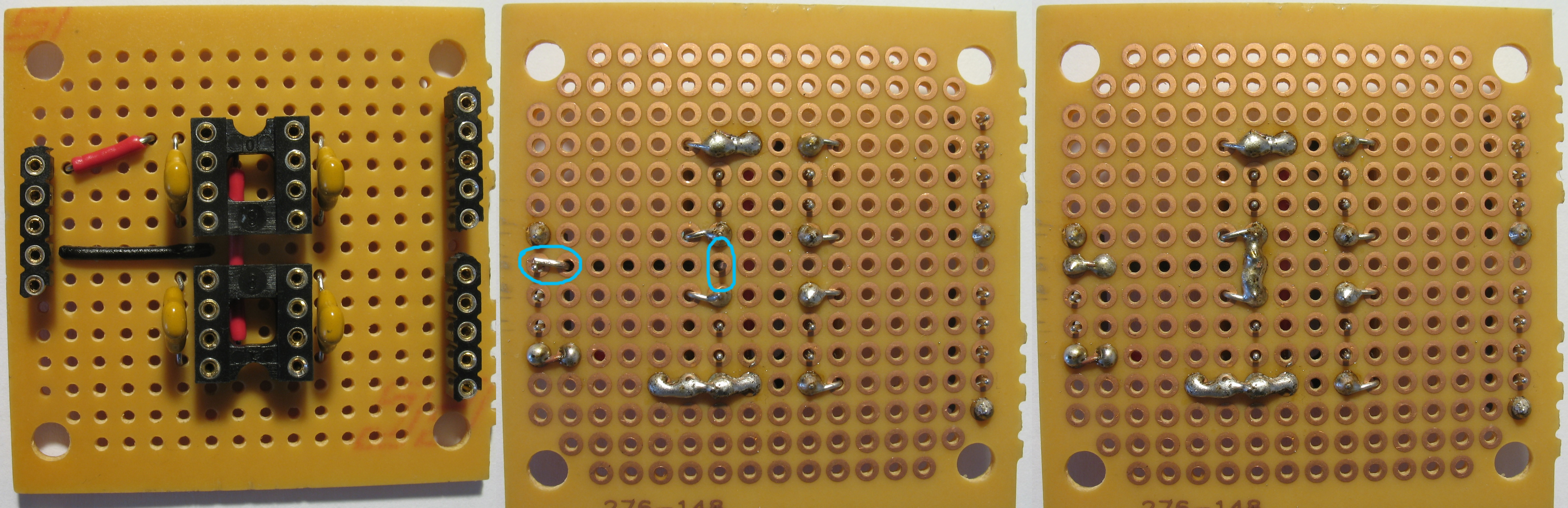
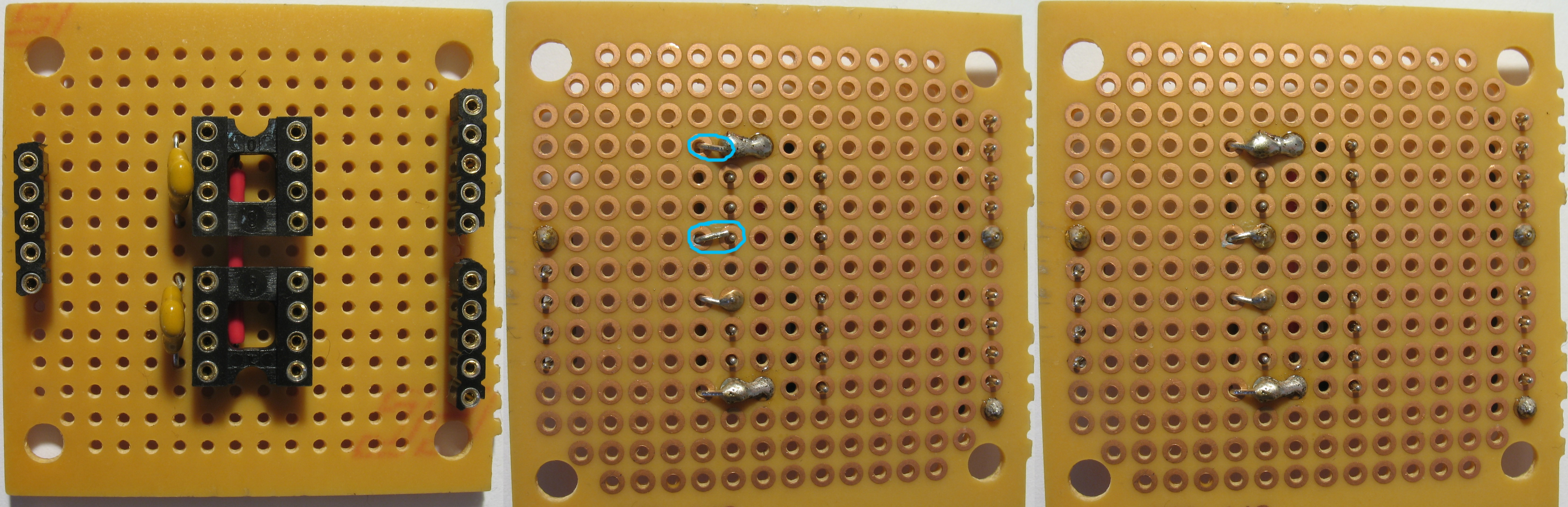
Solder the Networked Computer side Tx-wire between the Networked Computer side female header strip and Pin 2 of the upper DIP8 socket.
Solder the Networked Computer side Rx-wire between the Networked Computer side female header strip and pin 6 of the lower DIP8 socket.
Solder the Destination Computer side 5V VCC wire between the Destination Computer side female header strip and the lead of the nearest capacitor so that current can flow to pin 8 of the upper DIP8 socket.

Solder the Destination Computer side ground wire between the Destination Computer side female header strip and pin 5 of the upper DIP8 socket.
Solder the Destination Computer side Rx wire between the Destination Computer side female header strip and pin 6 of the upper DIP8 socket.
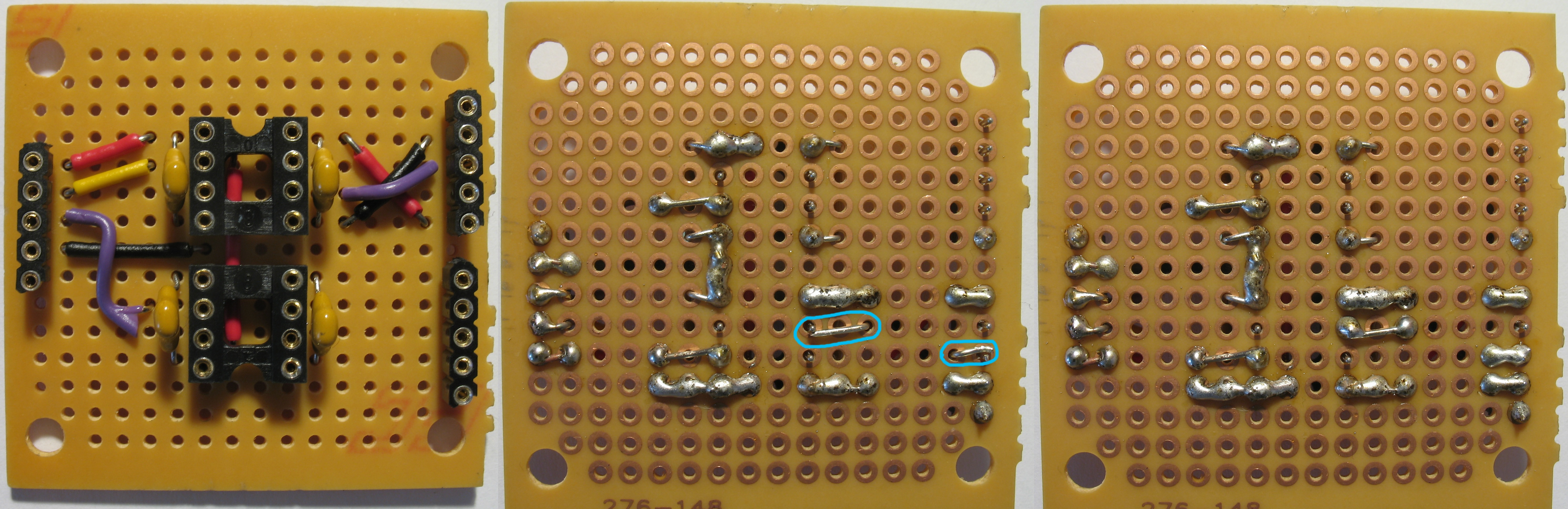
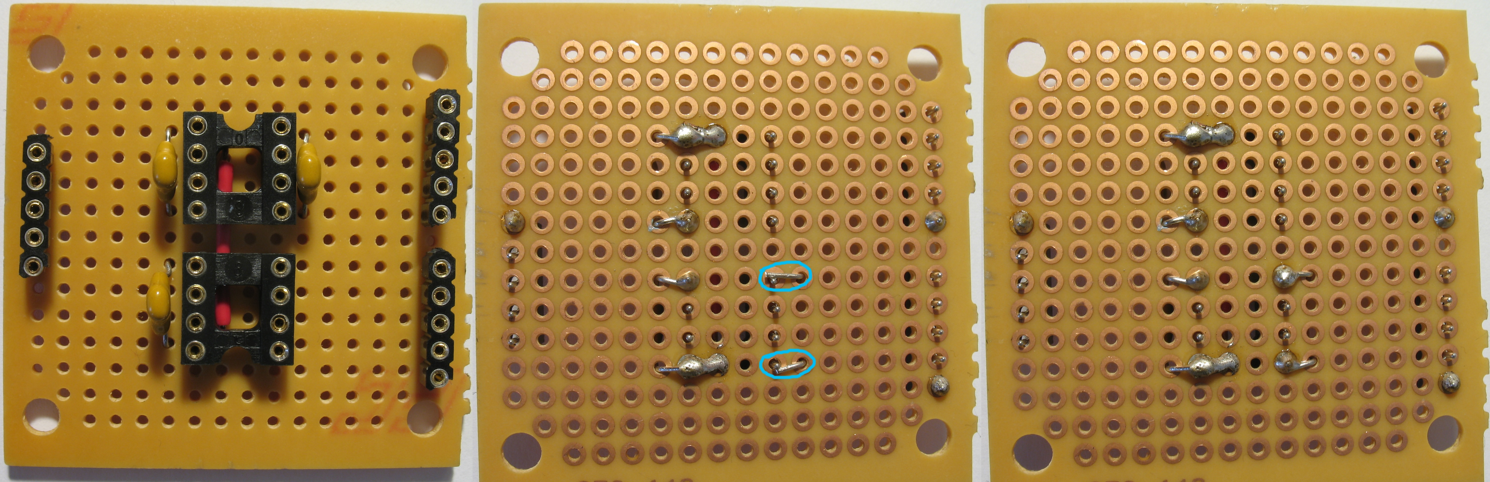
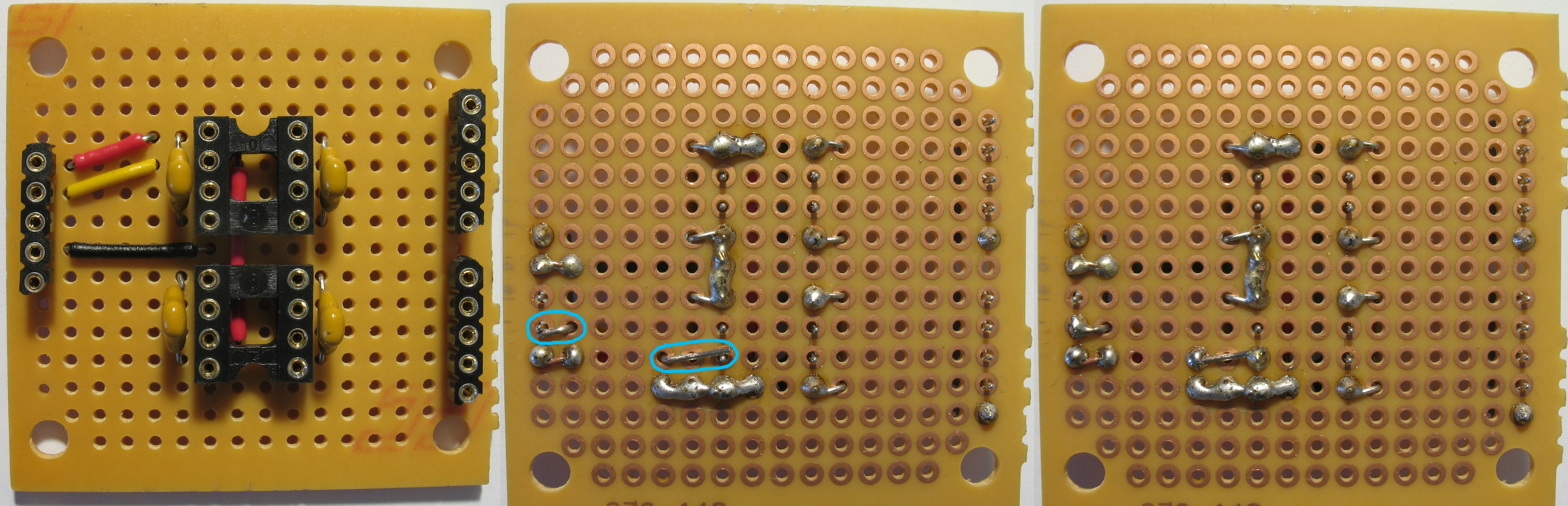
Solder the Source Computer side 5V VCC wire between the Source Computer side female header strip and the lead of the nearest capacitor so that current can flow to pin 1 of the lower DIP8 socket.
Solder the Source Computer side Tx wire between the the Source Computer side female header strip and pin 2 of the lower DIP8 socket.
Solder the Source Computer side ground wire between the Source Computer side female header strip and pin 4 of the lower DIP8 socket.
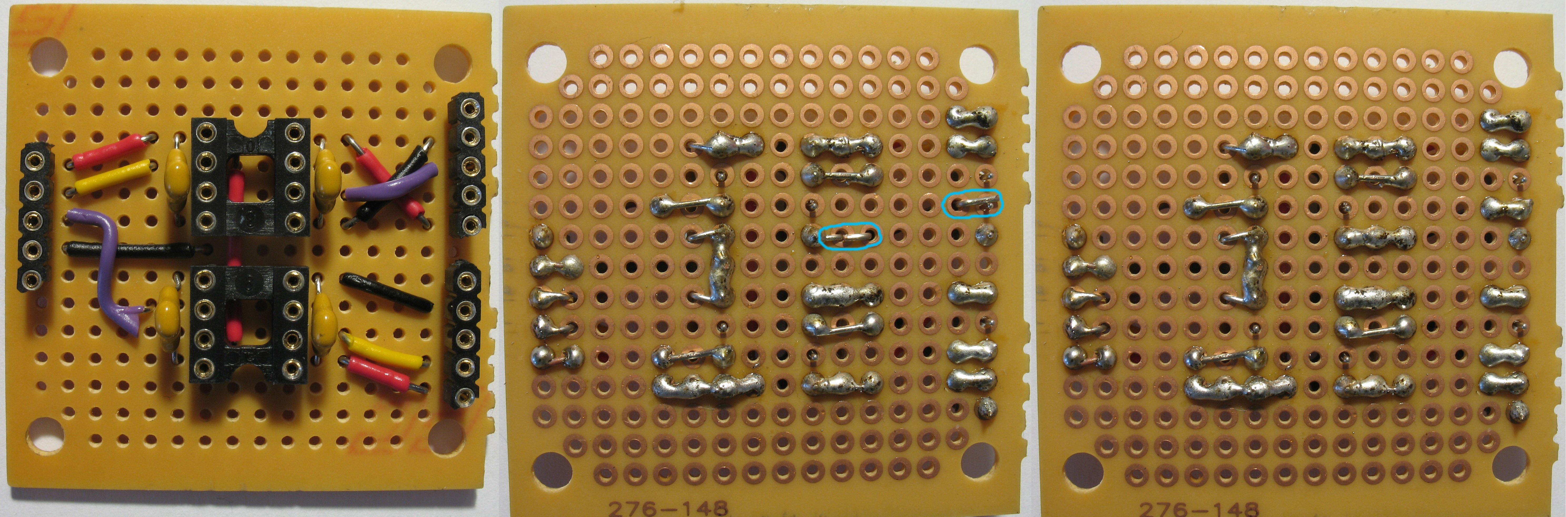
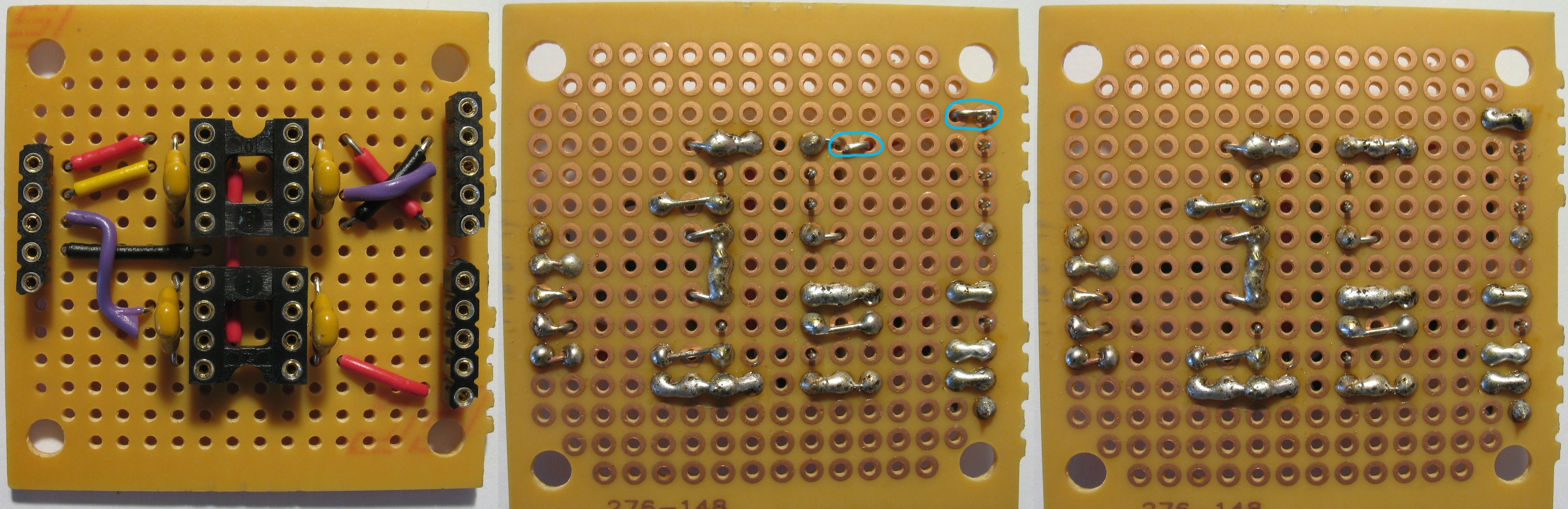
Connect the optocouplers to the DIP8 sockets. Make sure that the orientation marks (highlighted with blue circles) point to opposite directions. Connect the USB-to-TTL adapters to the data diode's female header strips.
If you want you can optionally create an inspectable tamper barrier for your data diode at this point.
The data diode is now complete. Connect the data diode between Source, Destination, and Networked Computer.