TTL Data Diode (PCB)
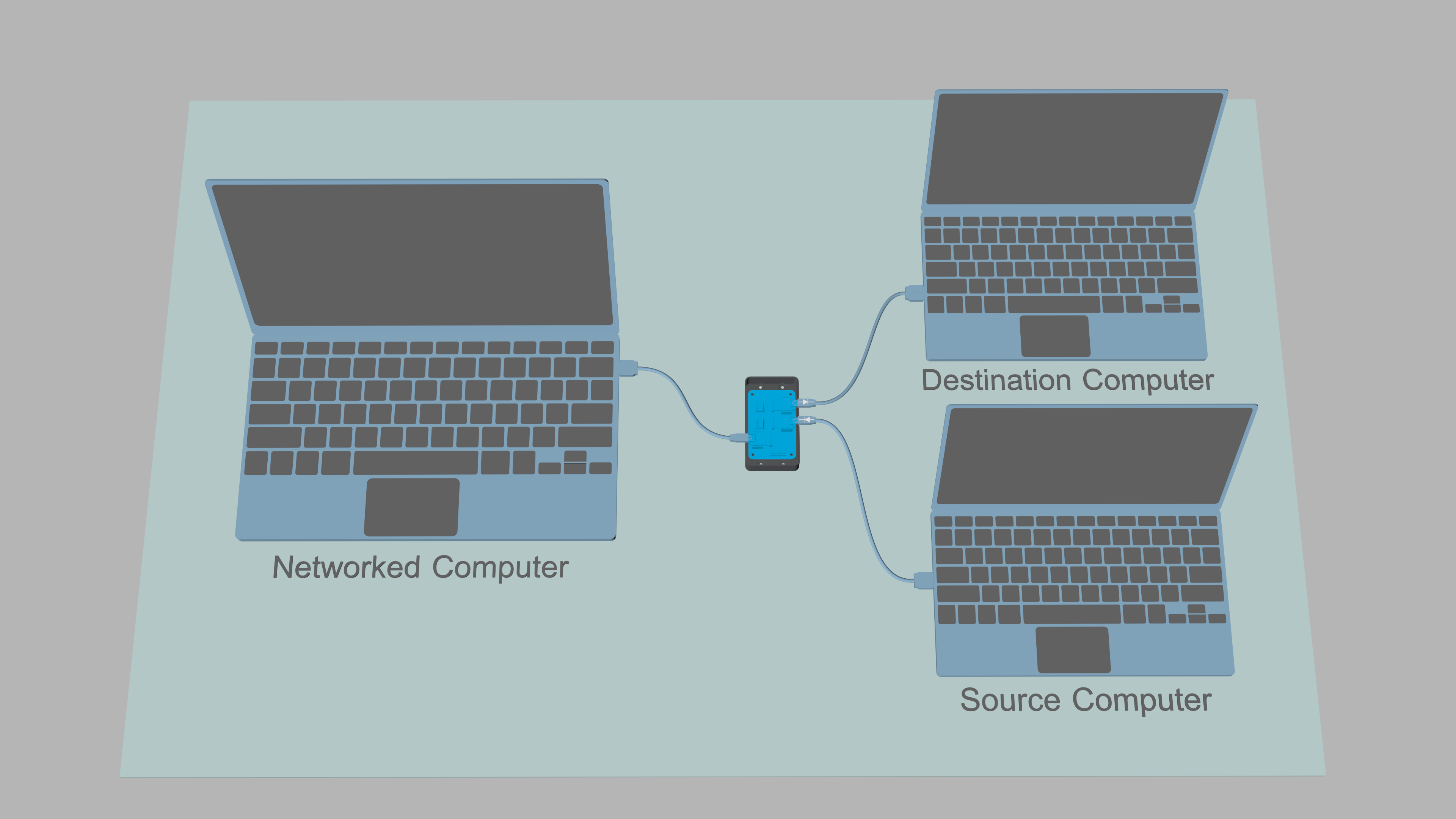
The hardware data diode is a device that allows transfer of data from one computer to another, while physically blocking transfer of data to the opposite direction. The data diode blocks all covert return channels of the link in question, even in the case where the serial interfaces (and their connected pins) are compromised, and re-programmed to send and receive data in the opposite direction.
The design of the data diode and this document are based on the USB-TTL-USB Data Diode (version 16.10.a) by the pseudonym Sancho_P. The PCB and the 3D-printable case are designs by cxcorp. The designs are modified and used under the GNU FDL v1.3.
| PCS | Item |
|---|---|
| 1 | Main board PCB |
| 9 | 5x1 male header (2.54mm) |
| 9 | 5x1 female header (2.54mm) |
| 2 | DIP8 socket |
| 2 | HCPL-7723 optocoupler |
| 4 | 0.01-0.1μF 0603 SMD capacitor |
| 3 | TTL-232R-5V USB-to-TTL adapter |
| 3 | USB 2.0 A - Mini-B cable |
| 1 | 3D-printed case |
| 11 | M3x6 metal screw |
| 9 | male-to-male jump wiring |
| PCS | Item |
|---|---|
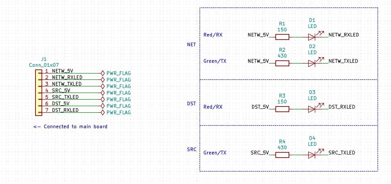
| 1 | LED board PCB |
| 2 | Green 0805 SMD LED |
| 2 | Red 0805 SMD LED |
| 2 | 150Ω* 0603 SMD resistor |
| 2 | 430Ω* 0603 SMD resistor |
| 1 | 7x1 male header (Straight, 2.54mm) |
| 1 | 7x1 male header (Right angle, 2.54mm) |
| 1 | 7x1-pin ribbon cable (~10cm long) |
As the original TTL-adapter is no longer available, the instructions below are informative only. Please refer to the schematics of the TTL-adapter to see how to connect the male-to-male jump wiring between the data diode and the TTL adapter.
The connections for the LED board are not available on the linked USB-to-TTL adapter.
* The actual resistor value will depend on the forward voltage and the current requirement of the chosen LEDs. Use this handy calculator if necessary.
As an optocoupler is an integrated circuit the internal functionality of which is hard to audit, to avoid interdiction by nation states, the user should avoid buying the component online. The main board PCB should be ordered without SMT assembly of optocouplers / FT232R circuits to distribute trust to different vendors and to mask the purpose of the optocouplers and the TTL adapters. However, capacitors, LEDs, resistors, and headers are most likely safe to order pre-assembled.
The circuit diagrams for the data diode are as follows
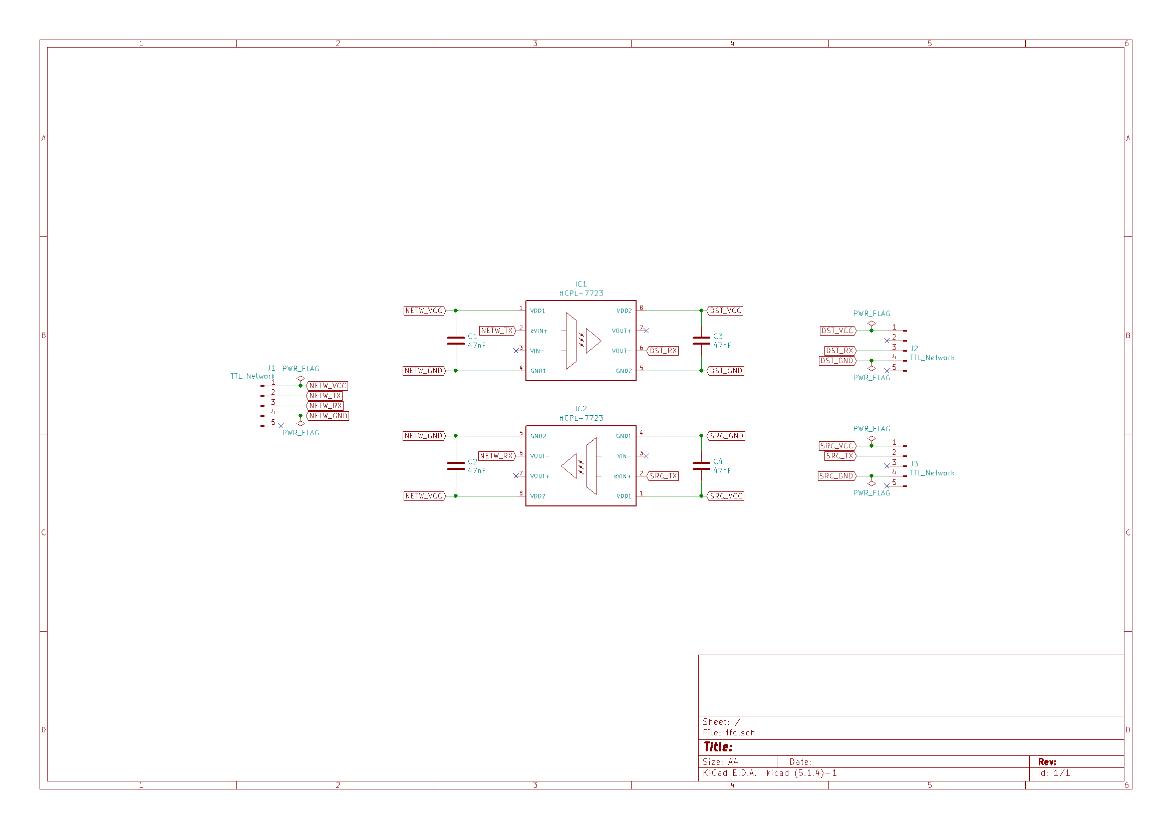
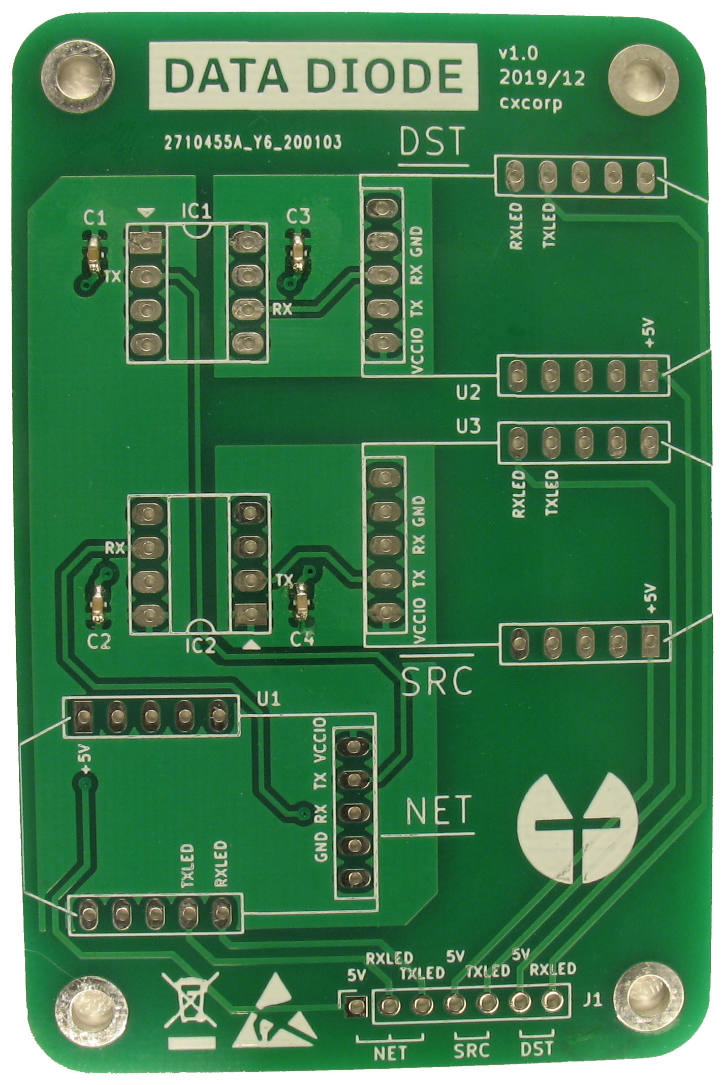
The main board circuit diagram
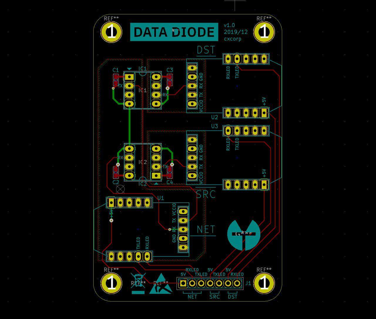
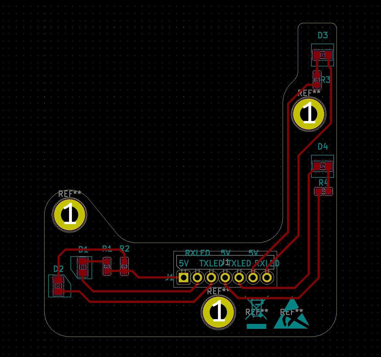
The PCB routing schematics are as follows:
You can download the gerber files for the PCBs below. The ZIP-files containing the gerber-files can be uploaded to e.g. JLCPCB or OSH Park, from where the PCBs can then be ordered. For personal safety when assembling, strongly consider selecting lead-free HASL (or other RoHS compliant finish such as ENIG) when ordering, despite its higher cost. The case has been designed to fit 1.6mm thick PCBs.
The STL-files for 3D-printing the data diode case can be downloaded from the links below:
-
Transparent LED covers for case top
Note: If you have access to a printer with two extruders, you can align the LED covers with the top of the case and print them with transparent filament.
Solder the capacitors to positions C1..C4 of the main board. Refer to e.g. this handy video on how to solder surface mount components.
Solder the female headers and the DIP8 sockets to the main board. Pay attention to the orientation of the DIP8 notches on the PCB. Also solder the straight 7-pin male header for the LED board if necessary.
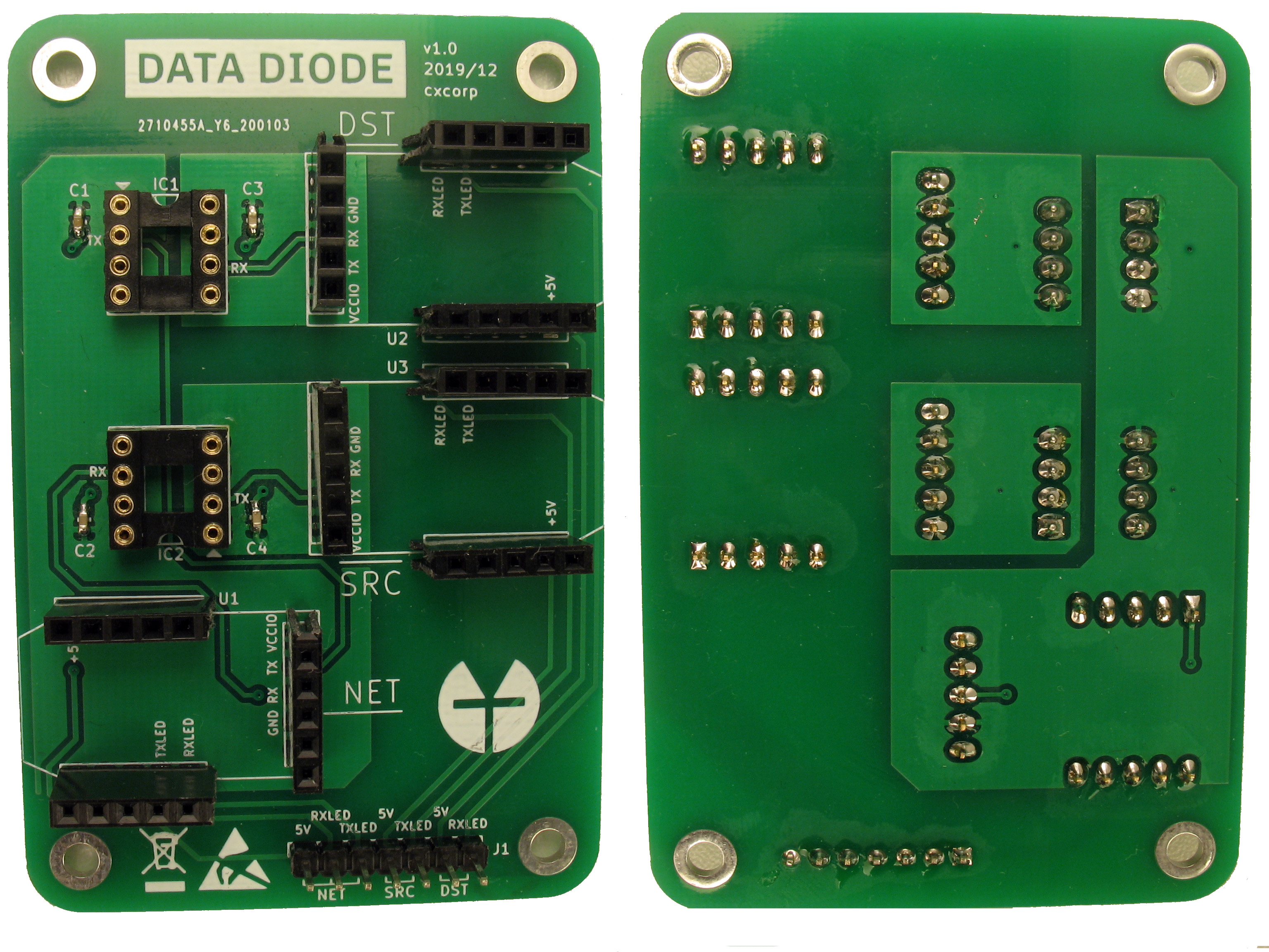
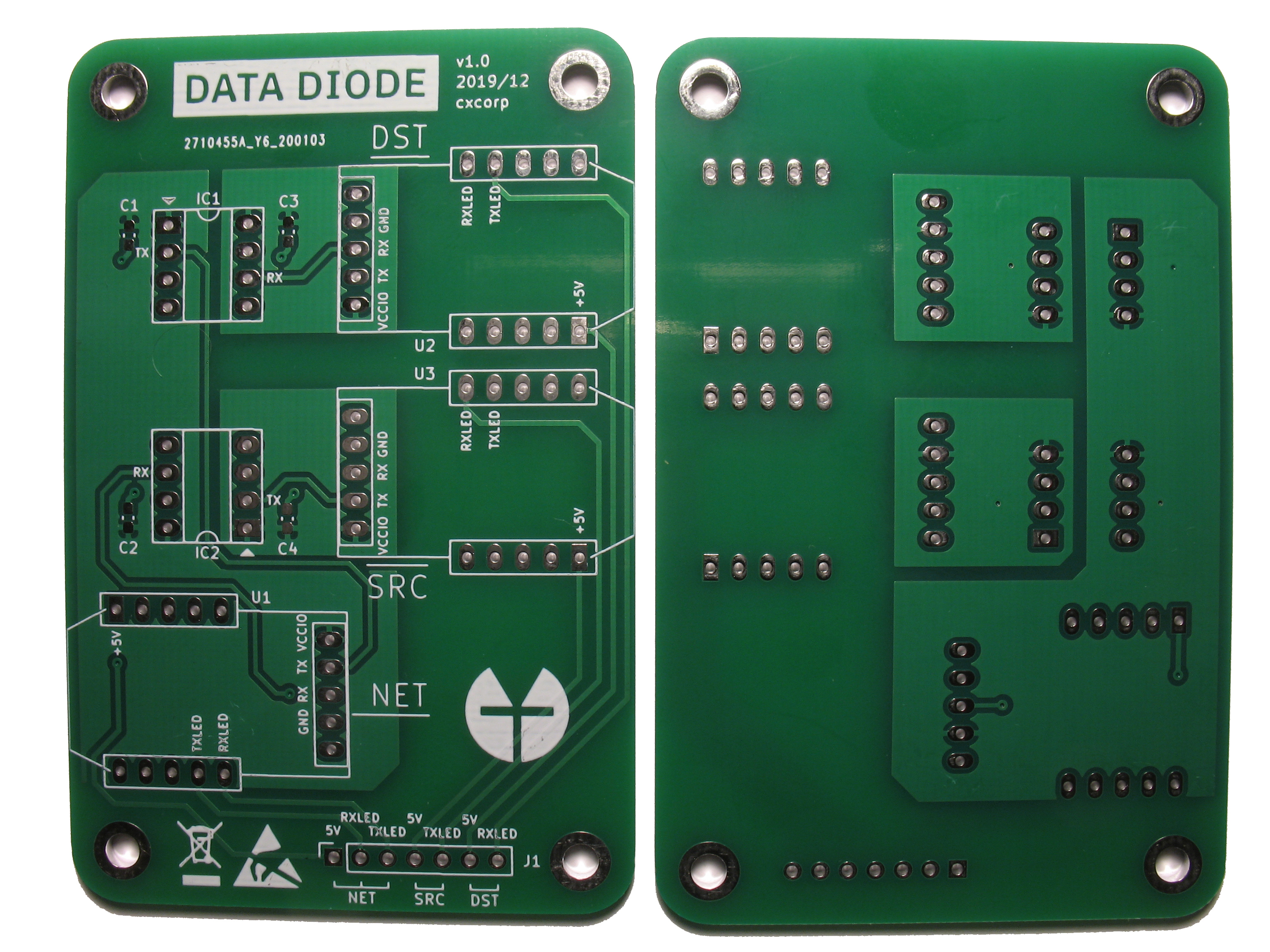
Main board with all components
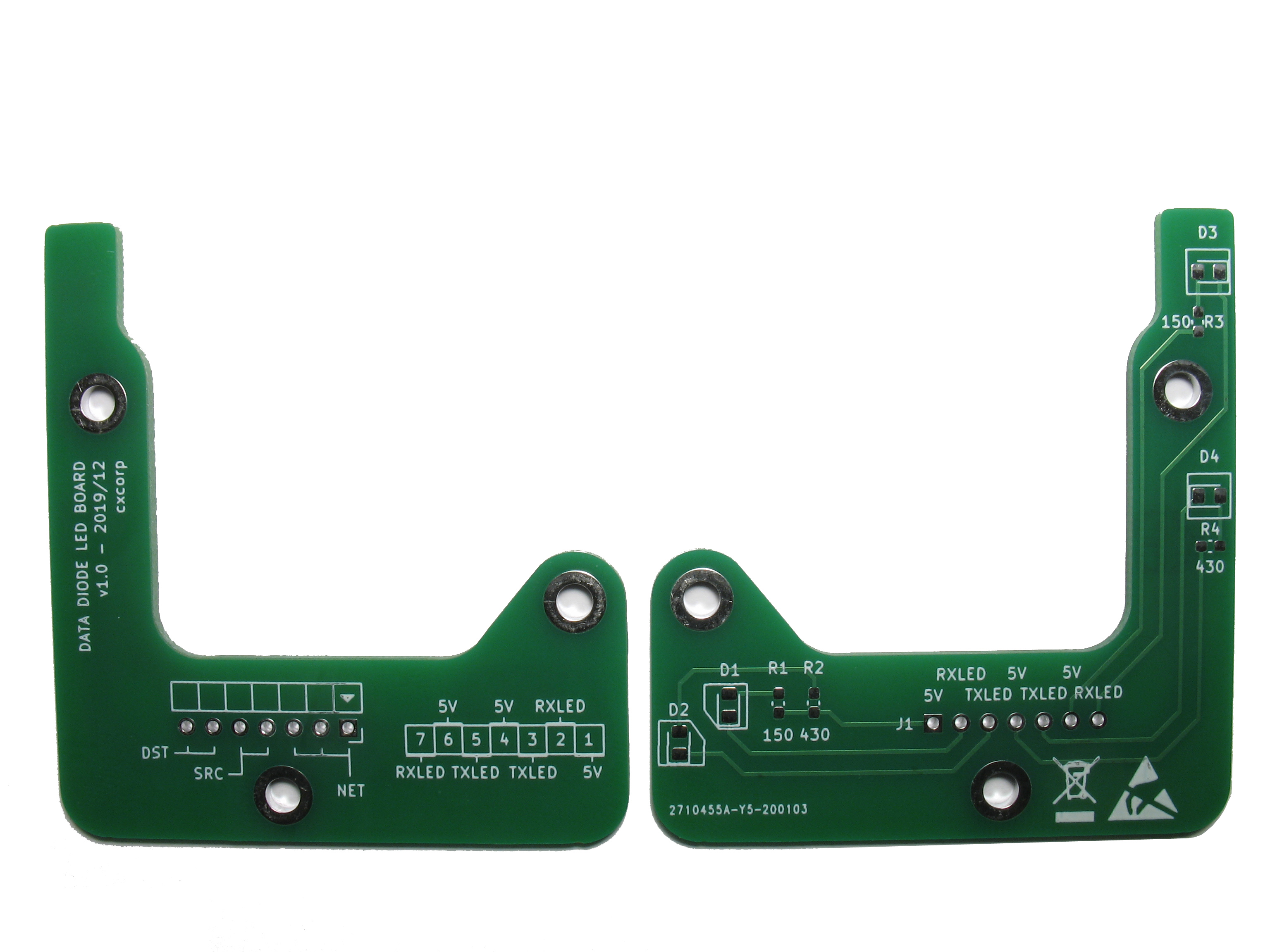
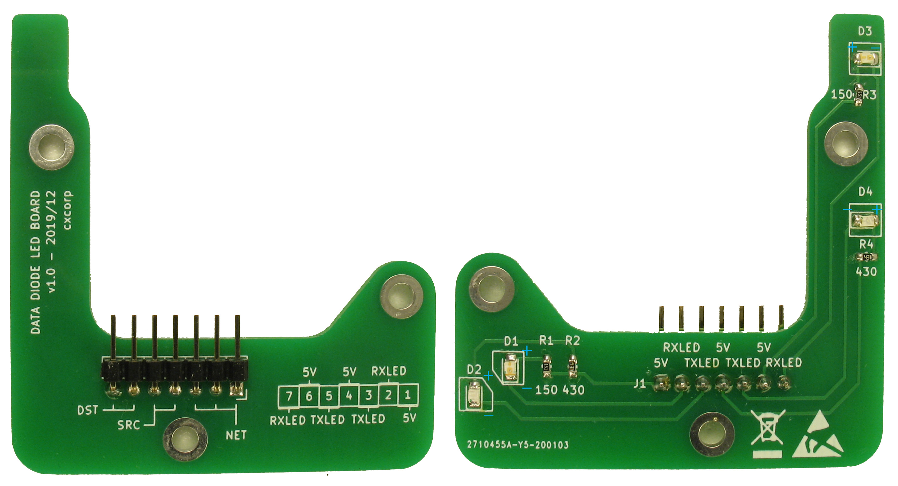
Solder the 7-pin right angle male header, the LEDs and the resistors on the LED board. The green LEDs are placed to D2 and D4, the red LEDs to D1 and D3.
Solder the voltage selector of each FT232R to the 5V setting. Pay attention to the picture below to see which sections the solder covers. Be careful not to bridge the V-shaped gap between the 3.3V source (pointed in red) with the center lead. Doing so will fry at least the TTL adapter once it's powered on. Solder three 5-pin male headers to each FT232R adapter.
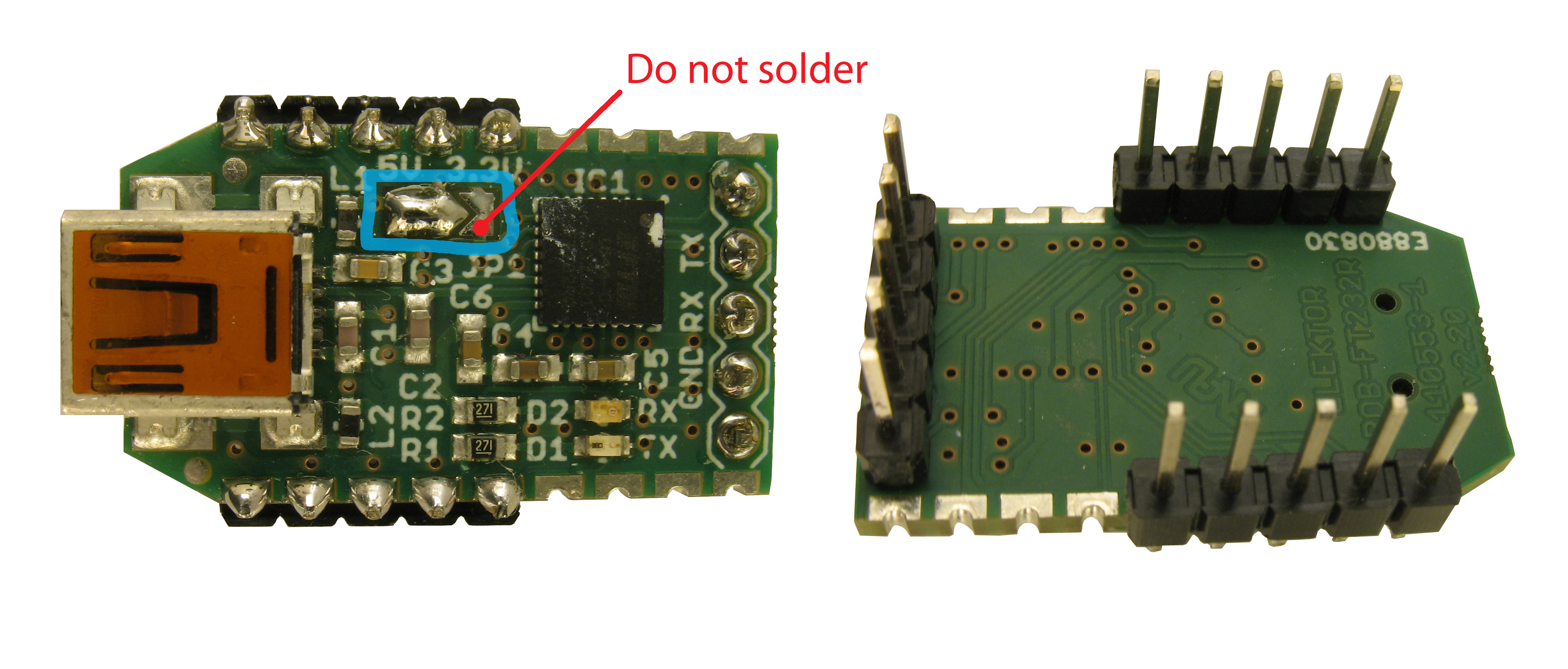
FT232R adapter with male headers
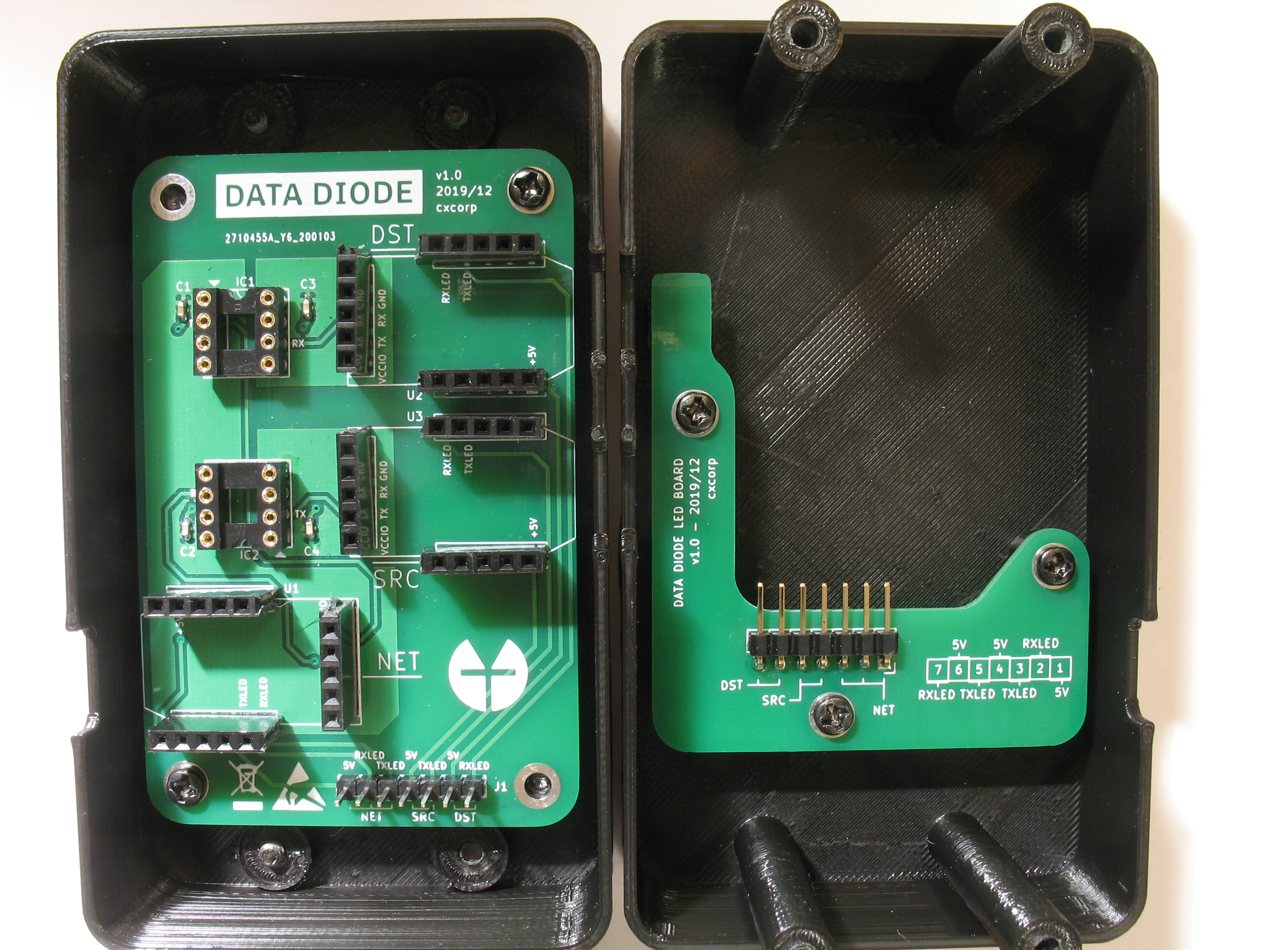
Attach the data diode main board and the LED board to the case.
Attach the optocouplers and the FT232Rs to the main board. Pay attention to the orientation marks of the optocouplers: they must match the PCB's (and if assembled correctly, the DIP8 sockets') notches.
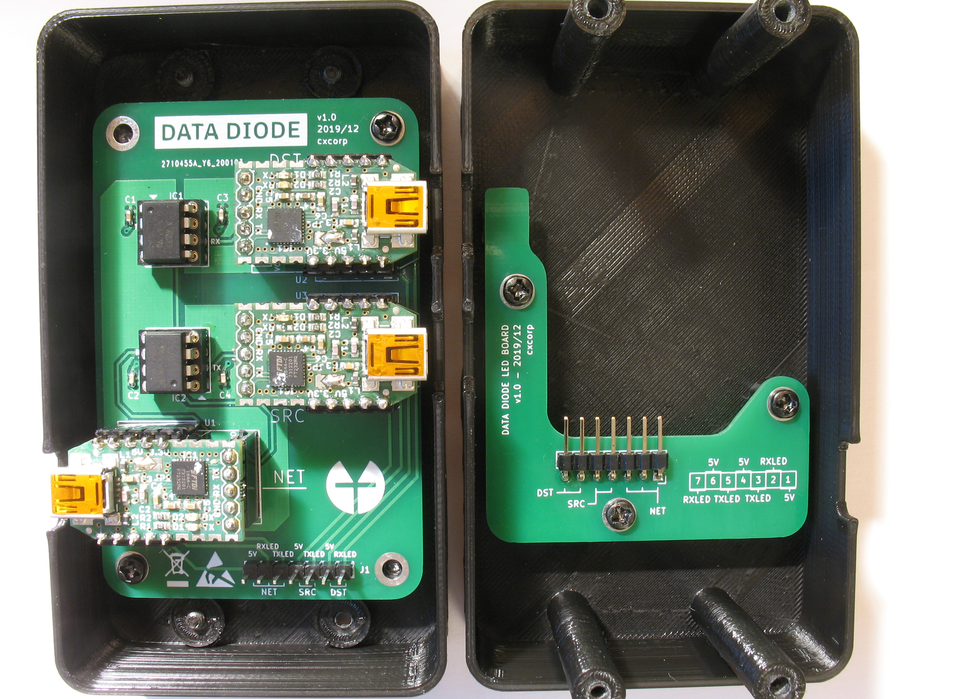
Data diode with optocouplers and FT232Rs
Attach the 7-pin ribbon cable between the two PCBs.
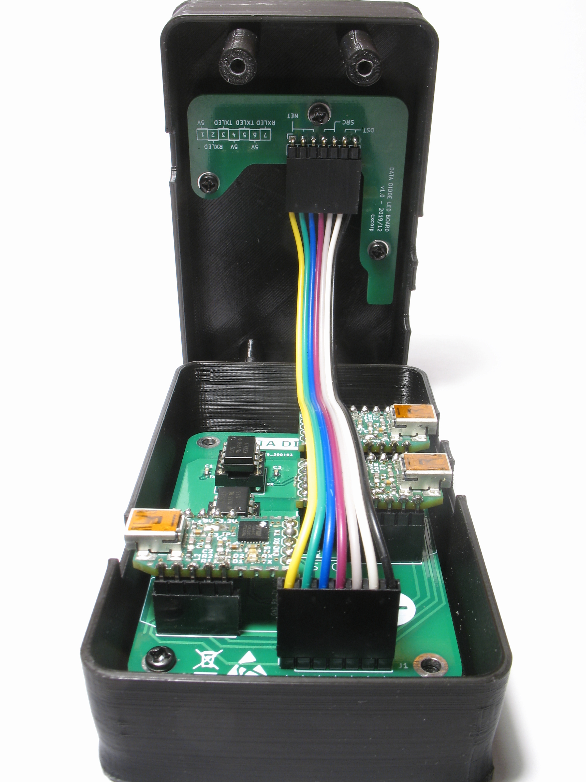
Ribbon cable connects main board with LED board
If you want you can optionally create an inspectable tamper barrier for your data diode at this point.
Close the data diode case.
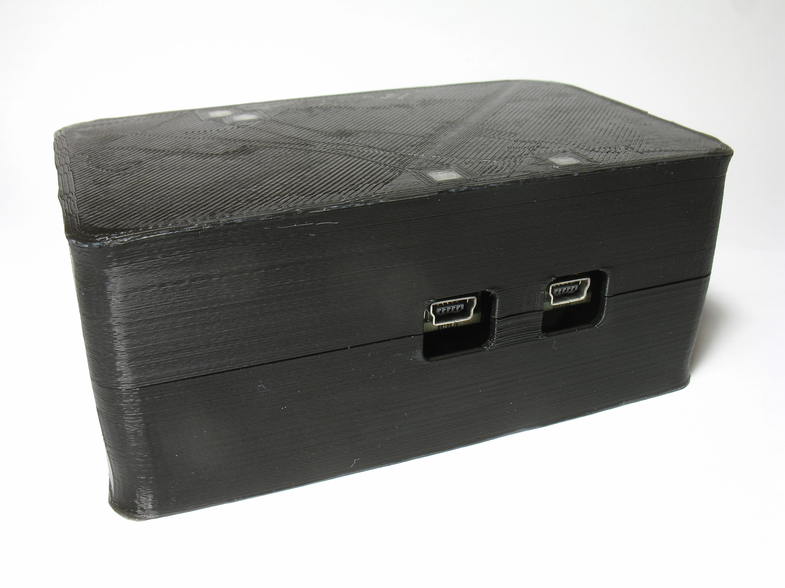
The data diode is now complete. Connect the data diode between Source, Destination, and Networked Computer.