Portability Topics
The Sensor Fusion User Guide provides guidance with regard to the process of porting the library from one board to another while using the Freescale toolset and existing template programs found at the Freescale sensor fusion page. But what if you want to use a different RTOS or Processor Expert is not part of your development tool suite? That's where this page comes into play.
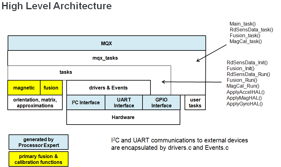
The basic architecture of the fusion library is shown in the figure below.
Let's start with hardware itself. You will save yourself a lot of time and trouble if you review Accelerometer placement - where and why and Magnetometer placement - where and why before you start your board design. You also want to make sure that you align the X/Y/Z axes for each sensor on the board. You can correct for misaligned sensors in the Hardware Abstraction Layer (or HAL) of your project, but why bother if you don't? Also make sure that you've aligned those sensors to the "natural physical alignment" of whatever your product is.
Hardware interfaces for the library were generated using the Freescale Processor Expert (PE) tool. Currently there are three:
- I2C
- UART
- GPIO
Sensor drivers in drivers.c have two C functions per sensor type: one to initialize the sensor and another that reads sensor values and writes those to the global structures corresponding to each sensor type. These drivers are layered on top of logical device drivers (LDDs) for I2C. Wired and wireless communication routines use UART LDDs. LED on/off are done with GPIO LDDs. All LDDs were generated using Freescale's Processor Expert tool.
You could manually replicate the PE-generated functions, taking into account your specific tool chain and hardware. But it is probably much easier to simply replace the routines in drivers.c with your own set of drivers. The Freescale project templates use polling mode at a common rate for all sensors. This is the simplest control structure possible, as the polling rate is defined to be equal to the high frequency task rate defined in the RTOS implementation. Depending upon the sensors used, you could save power by using sensor interrupt features to trigger sampling. This will come at the cost of some additional complexity.
drivers.c also contains routines for transmitting data packets via UART. Function BlueRadios_Init() can obviously be omitted if you are not using a Blue Radios Bluetooth module on your board. Function CreateAndSendBluetoothPacketViaUART() is really just the function which creates output packets based upon current operating settings and fusion results. You can consider this application specific, sitting on-top-of the fusion code. You can replace this with your own packet structure (or none at all), with no effect on the sensor fusion itself.
Events.c contains callbacks for a number of events associated with various hardware blocks. These are very lightweight functions (often only setting a status flag), and are inserted into the project via Processor Expert settings for MQX Lite. If you change hardware or RTOS, you'll probably want to rework these. One key function is UART_OnBlockReceived(), which implements the command interpreter for the embedded code. Consider this to be the sister function to CreateAndSendBluetoothPacketViaUART(). Together they implement the bidirectional communications protocol for the application. The current protocols match those of the Freescale Sensor Fusion Toolboxes for Windows and Android. If you keep these protocols, you can continue to use those tools for visualization purposes.
tasks.c provides a set of high level interfaces that will be used in mqx_tasks.c for RTOS integration. You will need to update tasks.c to account for changes in sensor sets (it calls the initialization and read sensor driver functions). But otherwise, you should be able to leave it pretty much alone so long as you don't want to mess with the magnetic calibration strategy. We suggest you leave it as is. There are numerous subtleties in the magnetic calibration that will not be immediately obvious. The current scheme is optimized for small, portable devices.
mqx_tasks.c defines tasks controlled by the RTOS. You probably want to keep the same task structure, regardless of RTOS, but you will have to modify the light weight event handling in this file to match your RTOS selection. It should be fairly obvious in the code where this needs to occur. Just search for
- _lwevent
- _task_create
- _task_destroy
You should have no need to change any of the following:
- magnetic.c
- fusion.c
- orientation.c
- matrix.c
- approximations.c
These core functions are expected to be stable from one implementation to the next. As much as possible, hardware and RTOS interactions have been abstracted in the layers described in the preceding sections.
It is certainly possible that the structure defined here may evolve with time as additional ports are implemented. Suggestions are welcome.
Open Source Sensor Fusion: Portability Topics by the MEMS Industry Group is licensed under a Creative Commons Attribution 4.0 International License.


- Open Source Sensor Fusion Overview
- [Portability Topics](Portability Topics)
- Tutorials
- Frequently Asked Questions
- Packet structure for the template programs
- Implementations