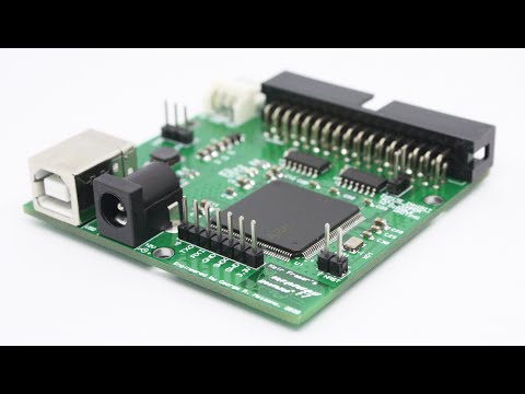
F7 Lightning Plus Assembly
NOTE: If you received a pre-assembled adapter then you can skip straight to Hardware Setup.
You should obtain (or have received) the following parts, in addition to the Greaseweazle PCB. Note that kits may include an excess quantity of the "passives" (resistors, capacitors).
| Board Reference | Footprint | Value/Type | Quantity |
|---|---|---|---|
| C2-C5,C14 | 0805 | 10uF1 | 5 |
| C9,C11,C13 | 0805 | 2.2uF | 3 |
| C1,C7,C17,28 | 0805 | 1uF | 4 |
| C8,C10,C12,C15-C16,C18-C27,C29-C31 | 0603 | 100nF | 18 |
| C6 | 0603 | 10nF | 1 |
| R1 | 0603 | 49.9k | 1 |
| R2 | 0603 | 9.53k | 1 |
| R3,R9-R11,R14 | 0603 | 1k0 | 5 |
| R4 | 0603 | 470R | 1 |
| R5-R6,R13,R15 | 0603 | 3k0 | 4 |
| R7-R8,R12 | CAY16 | 10k | 3 |
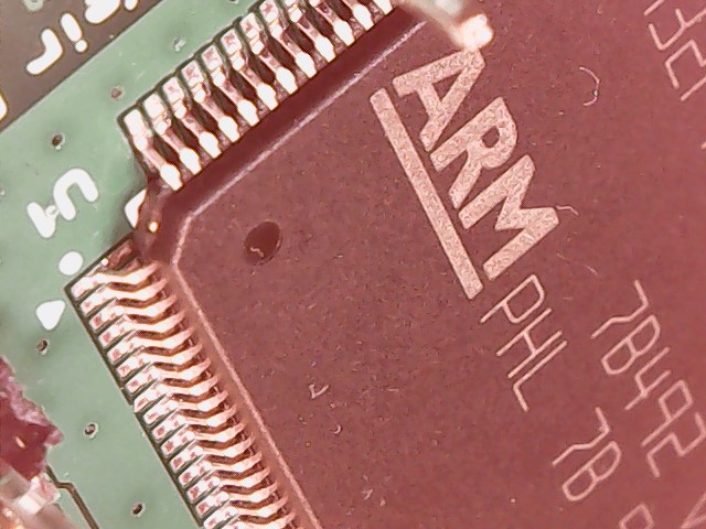
| U1 | LQFP144 | STM32F730Z8 | 1 |
| U2 | SOT23-6L | AP3211KTR-G1 | 1 |
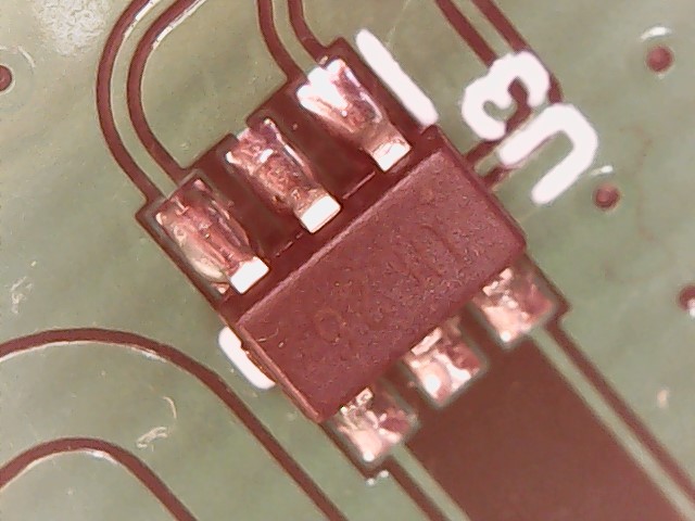
| U3 | SOT23-6L | USBLC6-2SC6 | 1 |
| U4-U5 | SOIC-14 | 74LS07 | 2 |
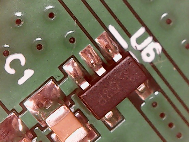
| U6 | SOT25 | AP2112K-3.3TRG1 | 1 |
| D1 | SMAF | SS22F, SS26F | 1 |
| L1 | 5mmx5mm | 4.7uH 2A | 1 |
| 12V | PRT-00119 | PRT-00119 | 1 |
| ACT | 0603 | G-Y LED | 1 |
| PWR | 0603 | Red LED | 1 |
| DEBUG | 7x1 | Pin Header | 1 |
| RESET, WRITE_INHIBIT | 2x1 | Pin Header | 2 |
| PWR_SLCT | 3x1 | Pin Header | 1 |
| FLOPPY POWER | 4x1 | TE 171826-4 | 1 |
| FLOPPY DATA | 17x2 | Box Header | 1 |
| USB | USB-B | 1 | |
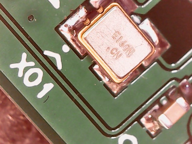
| XO1 | 4-SMD | ECS-3225MV-160 | 1 |
- C5 must be rated 16V or higher
Please note that the small size and pitch of some components, particularly U1, means that you will need some soldering proficiency, and equipment such as the following:
- A workbench with decent lighting
- Moderate magnification (eg. a magnifying bench light)
- Good quality leaded (60/40) solder (eg. Stannol, Kester)
- Avoid lead-free solder!
- Plenty of flux
- Tweezers
Although not a step-by-step guide, I will note some caveats.
-
The DIY kit comes with the STM32 chip placed in a fold of antistatic material, taped to the PCB. Be warned, the chip will be loose when you peel the tape!
-
The LED cathode terminal is marked by a green dot under the lens, which should be oriented towards the right-hand side of the PCB.
-
You may wish to remove pin 5 and/or pin 3 from the FLOPPY DATA header. Some floppy-drive cables use one of these pins as an orientation key.
-
The 10k resistor arrays are tight on their pads. Be careful that they are correctly aligned.
-
Jumpers are required at WRITE_INHIBIT (to enable writes) and at PWR_SELECT to select power from USB or external 12V supply.
-
Be careful not to use too much solder for the external oscillator (XO1). It is easy to flood solder up the side of the can and short the device. In this case the activity LED will flash three times repeatedly, at power on. You will need to try wicking up the excess solder. It may be safer to use hot air to attach XO1.
With thanks to Martijn Wieland.