Blue Pill Adapter
NOTE: If you received a pre-assembled adapter then you can skip straight to Hardware Setup.
NOTE: If you received a pre-programmed kit then you can skip straight to Through-Hole Assembly.
Directly connecting a "Blue Pill" to your floppy drive requires the following parts:
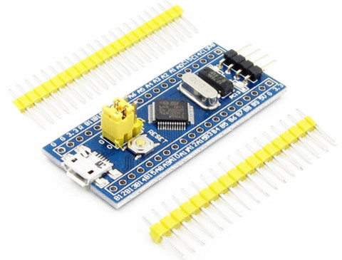
- STM32 "Blue Pill" board
- Adapter PCB
- 2.54mm-pitch Male Header Pins
- 4 x 0805 1k resistors
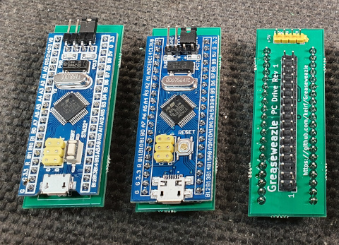
The "Blue Pill" is available very cheaply from many Chinese Ebay sellers for less than £2 including postage. The best search term is "STM32F103C8T6 board", sorted by lowest price first, and look for a board identical to below.
UPDATE: Please be aware of fake STM32 chips flooding the Chinese market. You may be advised to use a local source for your Blue Pill: For example, in UK they can be purchased for £3-4, you can more easily question a local seller, and you have wasted much less time if your chip does turn out to be fake.
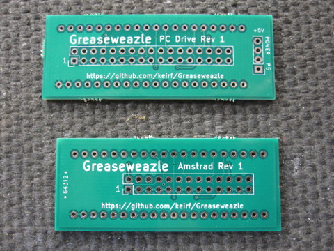
To source an adapter PCB, ask on the Facebook group page. Two types are available: One for 34-pin PC-compatible floppy drives, the other for 26-pin 3-inch Amstrad drives (used in CPC and Spectrum +3).
Alternatively you can have the PCBs made yourself:
DirtyPCBs: The simplest method, using a direct purchase link and costing approximately $25 in total. Once the design is added to your cart, be sure to increase the Size to 10x10, or your order will be rejected! You can also choose Color, and optionally increase Thickness to 1.6mm without increasing purchase cost. Your order will yield 10 PCBs, each containing 4 PC 34-pin adapters and 1 Amstrad 26-pin adapter: 50 in total!
Custom order (Gerbers): The Gerber sources for the 10x10cm panel as in the above DirtyPCBs store link can be downloaded here.
Custom order (KiCad): The original KiCad PCB design is available in my PCB Projects git repository. The single-board PC design is available under greaseweazle/, the Amstrad design under gw-26/, and the five-to-a-panel design (as in the DirtyPCBs store link) is under panels/GW. You will need to use KiCad to generate Gerbers.
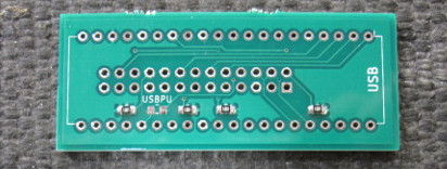
Solder four 1k 0805 resistors to the adapter PCB, skipping the location marked USBPU.
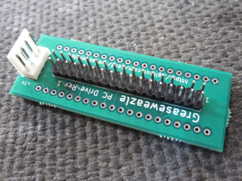
Solder male header pins to the floppy and power headers (note that the power header is omitted on the Amstrad adapter). On the PC adapter board I recommend that you remove header pin 5, as in the picture below (be careful of orientation and pin numbering!). This picture also illustrates use of a Berg power connector in place of 1x4 header pins.
Be careful to solder the pins straight: You may wish to solder one pin on each header, then heat that pin while ensuring the header is correctly seated. It is very hard to adjust after all pins are soldered!
Now solder the pair of 20-pin header strips to the Blue Pill, making sure they are straight, and solder the Blue Pill to the reverse side of the adapter board. Please note:
- The Blue Pill is a tight fit to the adapter: Make sure the pins are lined up, and expect to press firmly.
- Be careful not to press the Blue Pill fully flush with the adapter as you will risk shorting the backsides of the two boards against each other: Instead leave a small clearance of 1-2mm.
- Be sure to install your Blue Pill the right way round: The USB end is marked on the adapter.
Ensure that the boot jumpers are both set to 0, otherwise the Greaseweazle firmware will not run at power on. Note in the picture above that this setting has been soldered on the underside of the Blue Pill, and the boot jumper pins have been cropped: You do not need to do this.