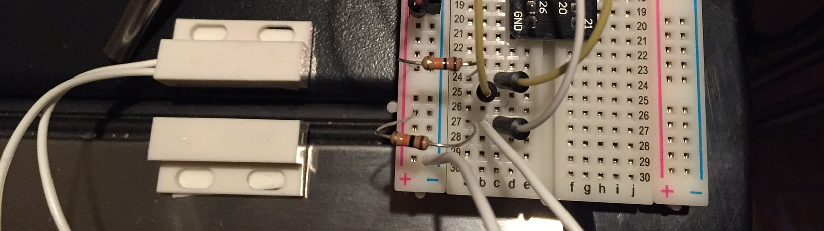
Part 3. Door Sensor
First, let's test the door sensor to make sure it is working. We will run the following Python script to test the door sensor:
https://github.com/InitialState/beerfridge/blob/master/switch_test.py
import RPi.GPIO as io

io.setmode(io.BCM)
doorPin = 17
io.setup(doorPin, io.IN)

doorStatusPrev = -1

## Event loop
while True:
    doorStatus = io.input(doorPin)
    if doorStatus != doorStatusPrev:
        if doorStatus:
            print "Open"
        else:
            print "Closed"
    doorStatusPrev = doorStatus
If you ran the "git clone https://github.com/InitialState/beerfridge.git beerfridge" command in Part 2, you already have this script on your Pi (otherwise, you need to create a switch_test.py script on your Pi from the above code). Run the following commands at a Pi terminal:
$ cd ~
$ cd beerfridge
$ sudo python switch_test.py
Open
Closed
Open
Closed
Open
Once this script is running, touch the flat ends of the switch together and pull them apart. The script should write "Open" or "Closed" to the prompt each time you do this. Notice that the switch does not have to make contact to be detected as "Closed".
NOTE: The reason you need to prefix "sudo" to the command that runs this script is because access to the general purpose input/output (GPIO) pins requires super users access. sudo (pronounced soo-doo) is short for "super user do"
Use two-sided tape or mounting tape to connect the door sensor to your refrigerator door. Make sure the side with the connected wires is on the frame of the refrigerator and the side without wires is on the door itself. With the switch_test.py script running, make sure the sensor accurately detects when the door is open and closed. CTRL+C stops the script.
<< Part 3: Wiring the Circuits - Part 3: Temperature Sensor >>