Home
Bearnav is a simple teach-and-repeat visual navigation system robust to appearance changes induced by varying illumination and naturally-occurring environment changes. It's core method is computationally efficient, it does not require camera calibration and it can learn and autonomously traverse arbitrarily-shaped paths. During the teaching phase, where the robot is driven by a human operator, the robot stores its velocities and image features visible from its on-board camera. During autonomous navigation, the method does not perform explicit robot localisation in the 2d/3d space but it simply replays the velocities that it learned during a teaching phase, while correcting its heading relatively to the path based on its camera data. The experiments performed indicate that the proposed navigation system corrects position errors of the robot as it moves along the path. Therefore, the robot can repeatedly drive along the desired path, which was previously taught by the human operator.
The navigation system works in two steps: teach and repeat. During the learning phase, a robot is guided by an operator along a path, which is the robot supposed to autonomously navigate in the repeat phase. When learning, the robot extracts salient features from its on-board camera image and stores its current traveled distance and velocity. During autonomous navigation, the robot sets its velocity according to the traveled distance and compares the currently detected and previously mapped features to correct its heading.
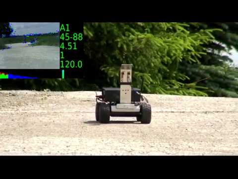
During this phase, the robot is driven through the environment by a human operator. The robot continuously measures the distance it traveled and whenever the operator changes the forward or angular velocity, the robot saves the current distance and the updated velocity values, a.k.a path profile. Additionally, the robot continuously extracts image features from its on-board camera image and every 0.2~m, it saves the currently detected image features in a local map, which is indexed by the current distance the robot traveled. Video 1 shows an early version of the system while learning. Note the image features detected in the on-board camera image of the robot.
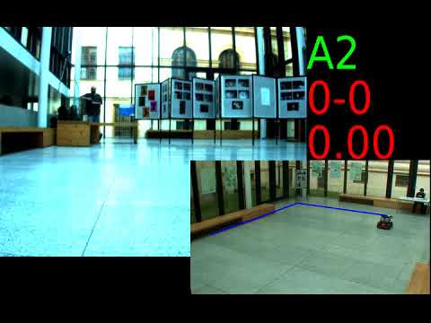
During the navigation phase, the robot traverses the learned path by itself using the speeds in the path profile and visual features in the local maps. The path profile is simply 'replayed', i.e. the robot sets a relevant steering and forward velocity according to the distance traveled. The local maps are used to correct the robot heading. Videos 2 and 3 show an early version of the system
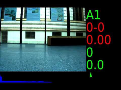
where robots traverse a polyline-shaped path. When moving, the robot retrieves image features from a relevant map (green crosses), extracts image features from its on-board camera (blue crosses), matches them (green/blue lines) and calculates a histogram of their horizontal distances (green). The histogram maximum is then used to steer the robot close to the learned path.
The navigation system is implemented in Robotic Operating System (ROS), version Kinetic. It requires that the robot hardware publishes /odom, /joy and /image topics and listens to the /cmd topic. The system composes of several nodes:
- Feature extractor node extracts image features from the robot camera and passes them to the mapping and navigator nodes.
- Distance monitor node receives data from robot odometry, measures traveled distance and notifies the mapper node to create an additional map every time a given distance was traveled.
- Mapper node receives features from the feature extractor node and saves them into local map whenever it receives the aforementioned message from the distance monitor node. It also saves the path profile.
- Map preprocessor node loads all local maps and path profile, sends them to the navigator node based on the traveled distance received from the distance monitor.
- Navigator node receives the velocity profile and local feature maps. Then it matches the features from the maps to the currently visible features from the feature extractor node, performs the histogram voting, calculates the robot velocity and steers the robot along the path.
\begin{figure} \begin{center} \includegraphics[width=0.85\columnwidth]{fig/system} \caption{Software structure of the presented system\label{pic:system}} \end{center} \end{figure}
All the aforementioned modules are available as C++ open source code at~\cite{github}.