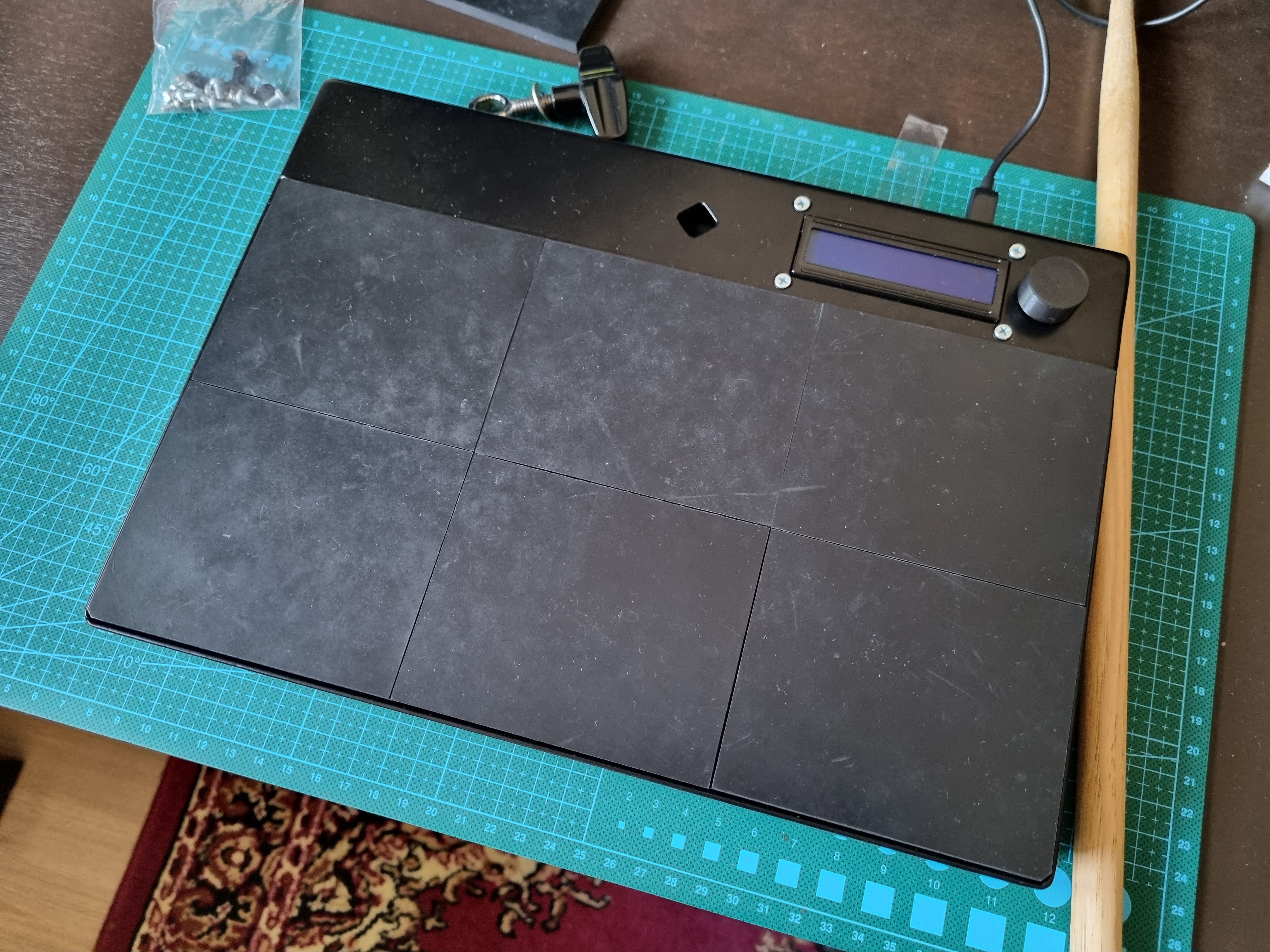
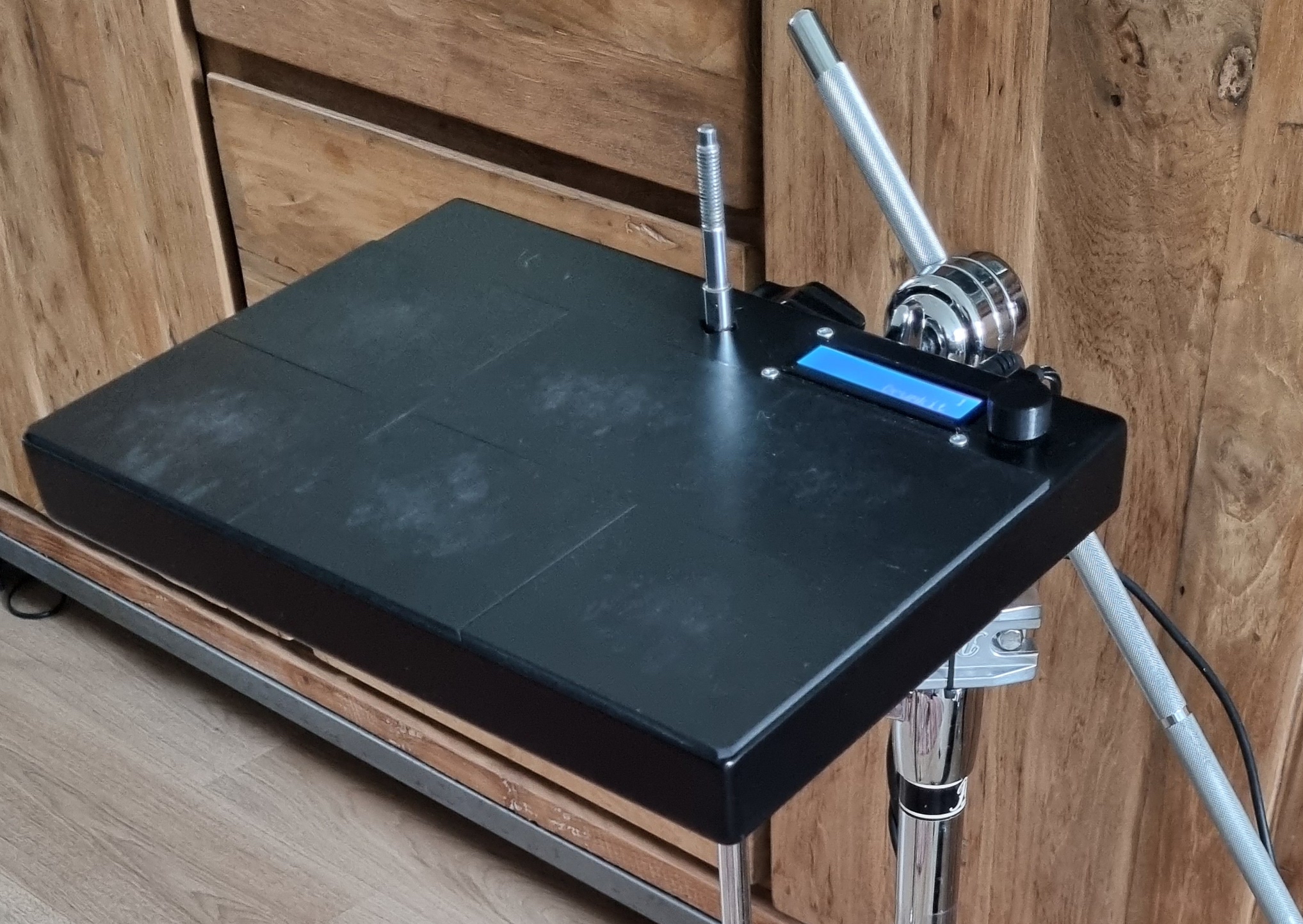
TeensyDrum is a 6 pad Midi Drum Pad powered by a Teensy 4.0. Expanded by 2 external inputs and 2 footswitch inputs it's a gig ready device. The book size device mounts to standard drum hardware. Hits on the pads are registered by a FSR sensor where the velocity is determined by piezo elements. The 1602 LCD in combination with the encoder makes it possible to navigate through the menu and change settings. A total of 9 saveslots are available to save the different settings. Names of the slots are changable.
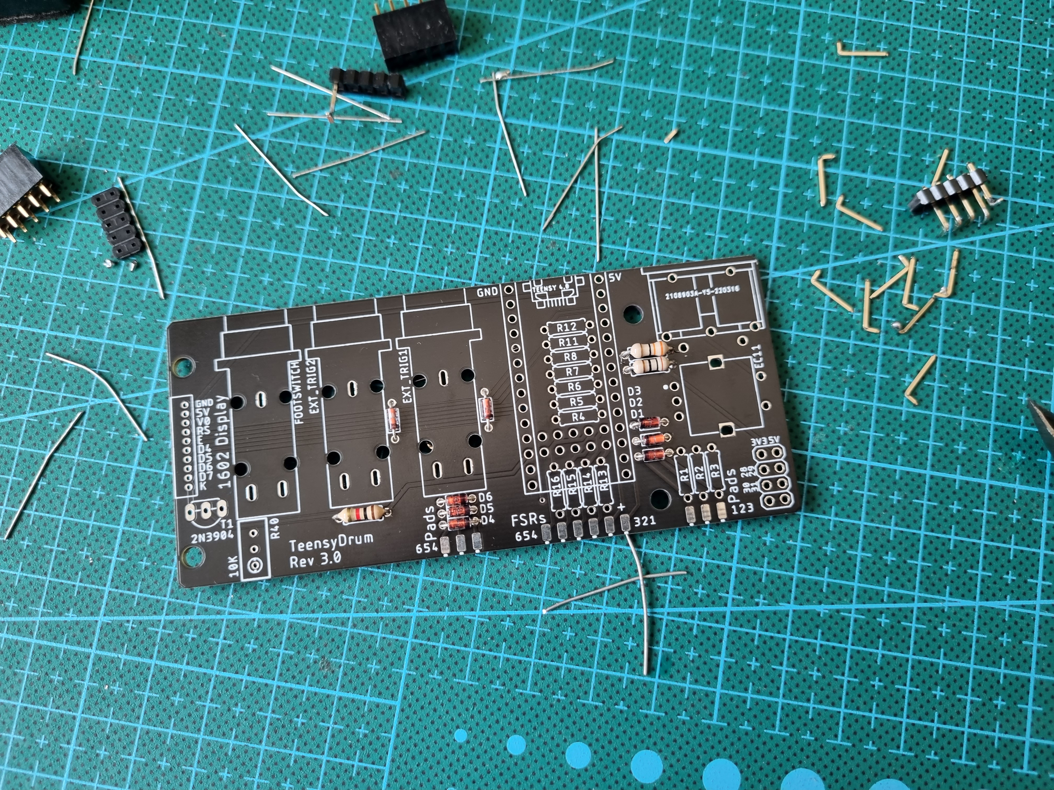
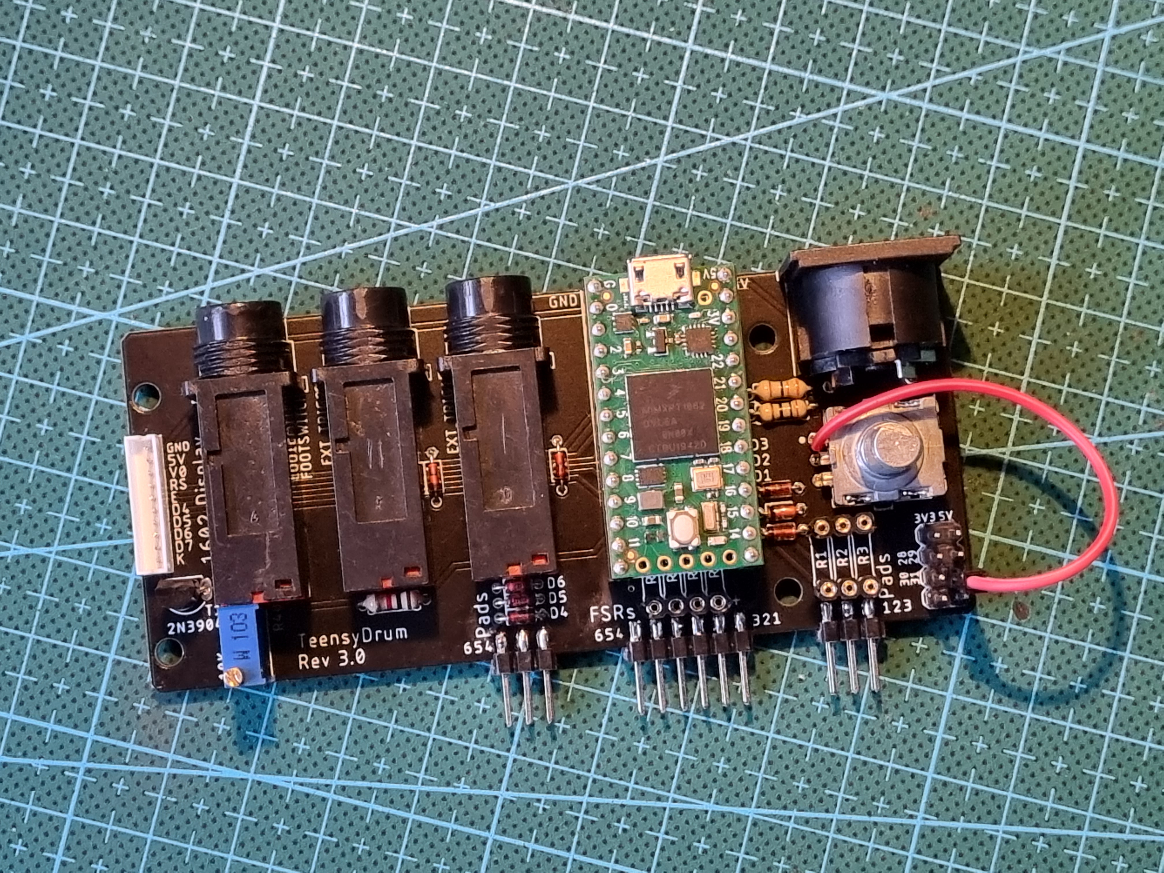
The PCB contains a Teensy 4.0 on headers, using the extra pins 24-33 on the bottom. On the right-hand side a DIN-MIDI connector is added for MIDI output only. Just below that is a toothed encoder to navigate through the menu. The FSR's and Piezo's connect to the double headers on the bottom side. Left of the Teensy are the 1/4" jack sockets for external triggers and footswitches. On the far left is the JST connector for the 1602 display. The transistor is used for the brightness of the display.
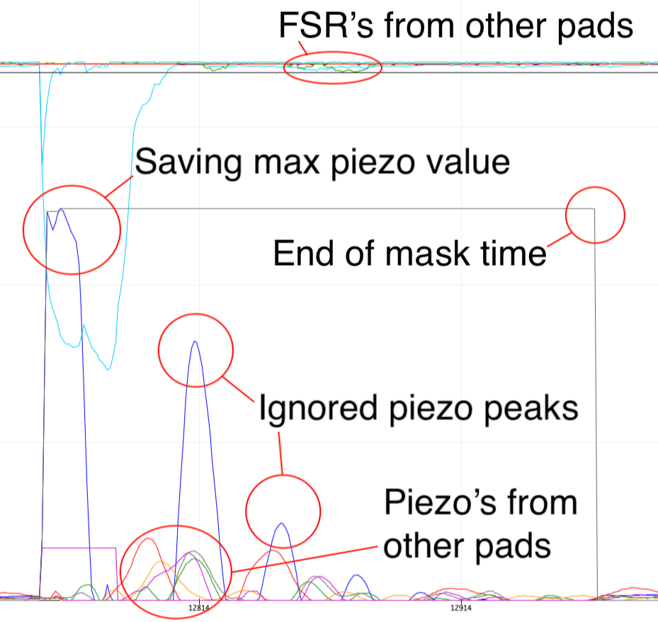
To determine a hit, the following happens: If the difference of the FSR value is high, the scan period is activated. Within the scan period the max value of the piezo is saved. As soon as the scan period ends, a midi signal is sent. Piezo peaks outside of the scan period are ignored. New hits are ignored as long as the mask time is active. As you can see, a hit will make other piezo's vibrate as well, but since the FSR's from other pads aren't detecting a hit, these piezo's are ignored.
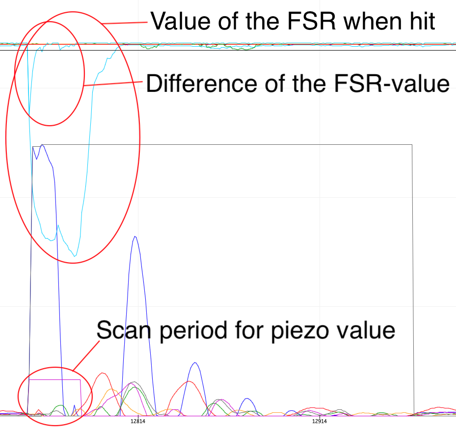
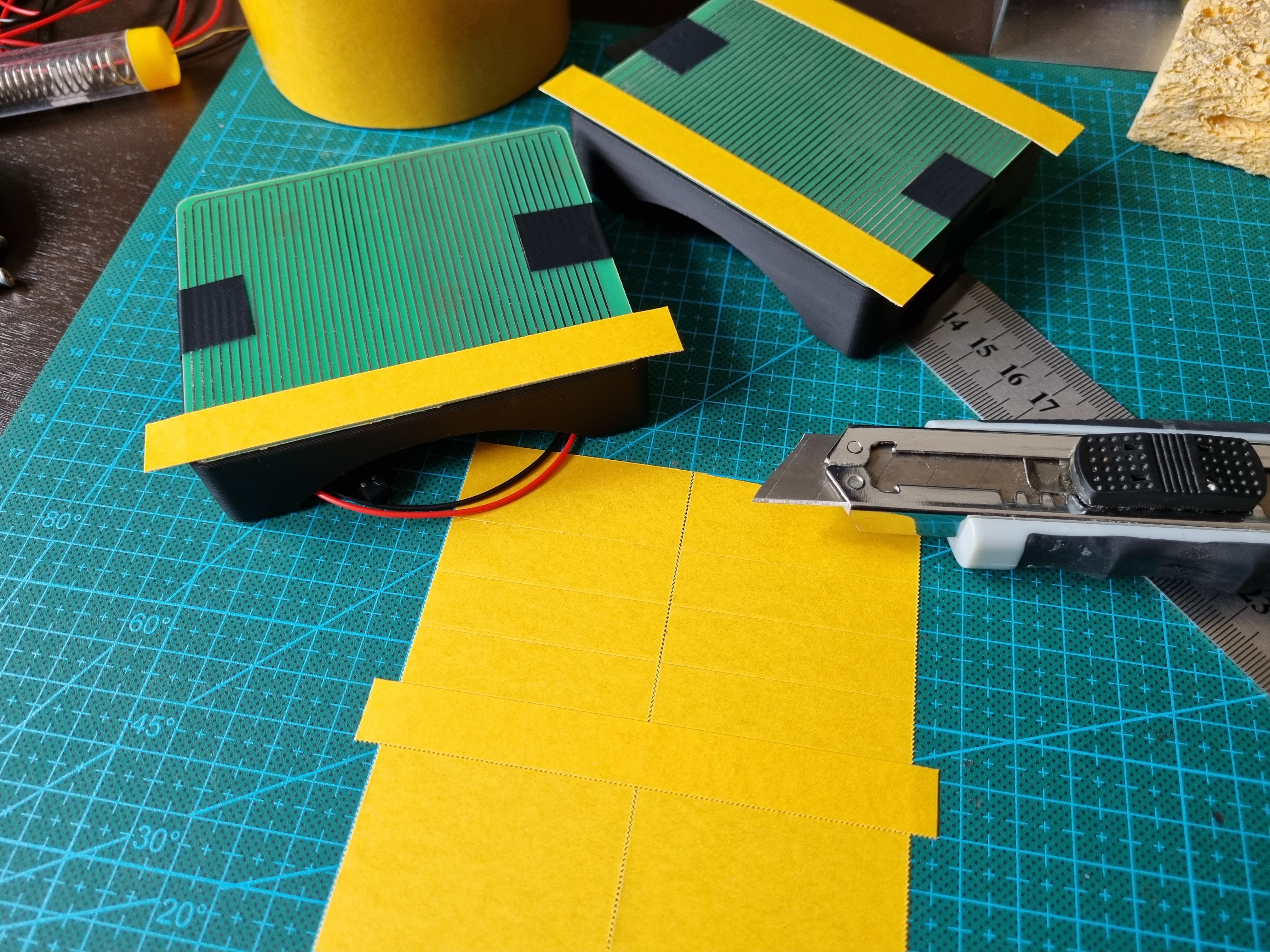
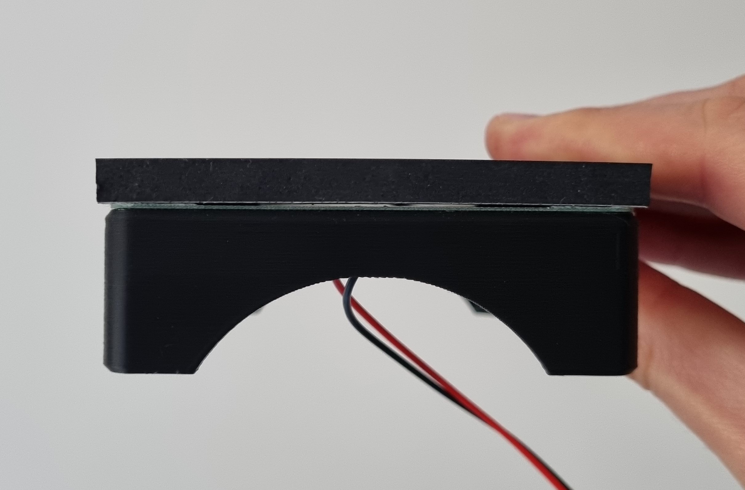
The FSR sensor is a home-made sensor. It consists of a thin PCB with open copper traces and a layer of velostat. When pressure is applied to the velostat, the resistance will drop. Together with a resistor, this is made into a voltage devider. The voltage is measured by the analog input of the Teensy.

The traces on the PCB are 2 combs with alternating fingers. The layer velostat is taped to the PCB using dubble sided tape. This leaves a small gap between the velostat and the PCB, resulting in a disconnected "R2". The Teensy measures 3.3v. If a pad is hit, the velostat will connect the 2 combs resulting in a quick voltage drop.
- Pad 1
- Command
- Note On
- Note Value
- Note Velocity
- Back
- Control Change
- Control Number
- Control Value
- Back
- Program Change
- Change Load Slot
- Back
- Note On
- Channel
- Threshold
- Scan Time
- Mask Time
- Back
- Command
- Pad 2
- See Pad 1
- Pad 3
- Pad 4
- Pad 5
- Pad 6
- Trigger 1
- Trigger 2
- Footswitch 1
- Command (Same as Pads)
- Channel
- Polarity
- Mask Time
- Back
- Footswitch 2
- Brightness
- Save Settings
- Load Settings
- Exit Menu