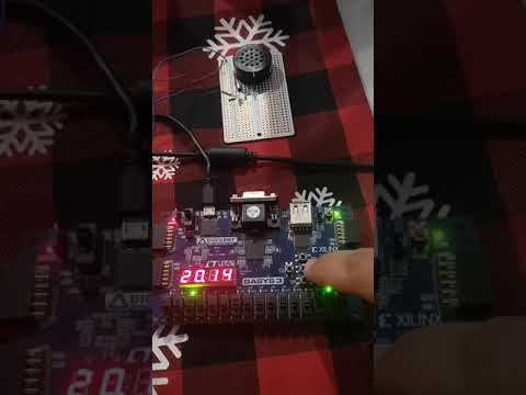
Digital clock implemented in vhdl for the Basys 3 Board from Digilent. Small project to complete the VHDL class of the Master degree program Master in Engineering of Electrical engineering registered at the Facultad de Mecanica y Electrica (FIME) of the UNIVERSIDAD AUTONOMA DE NUEVO LEON.

and the schematic can be found here: link to schematic
- Debouncer
- Decoder from binary to bcd
- Decoder from bcd to 7 segment display
- Clock divider with multiple output frequencies
- Button menu
- LED animated ( shift from left to right and right to left)
- Buzzer alarm sound ( at 200Hz between G3 (196.00Hz) and G#3/Ab3 (207.65Hz) )
############### THE BUZZER ###############
Connect the buzzer to JA4, you can use a simple BJT 2N2222 Transistor connected in saturation mode (emitter to GND and collector to one of the buzzer termination), the other buzzer termination is connected to VCC. Remember to use a diode betweeen the emitter to collector of the BJT, the anode of the diode to the emitter and the catode to the collector to let the the current in inductance flow back to the source. You might use a 1K ohm resistor in series with the base (I didn't use it).
############### THE LEDS ###############
When LED 0 and LED 1 are OFF the data displayed is the current clock When LED 0 is ON and LED 1 is OFF the data displayed is the new clock to set
############### THE BUTTONS ###############
-
When LED 0 is OFF and LED 1 is ON the data displayed is the alarm
-
To enter in setting mode, to configure or check the new clock or alarm data press the center button (BTNC).
-
To select a digit from the 7 segment display it is neccesary to use the right button (BTNR). When the digit is selected it will be blinking at 500ms.
-
To change the digit value, it is neccesary to use the up button (BTNU).
-
To set the new clock into the current clock it is neccesary to press left and down button (BTNL and BTND) at the same time for 1 second.
############### THE SWITCHES ###############
-
When SW0 and SW1 are ON or OFF, the current clock will count every second
-
When SW0 is ON and SW1 is OFF, the counter will increase 10 time faster (every 100 milisecond)
-
When SW0 is OFF and SW1 is ON, the counter will increase 100 time faster (every 10 milisecond)
############### THE DISPLAY ###############
The display has 4 digits and 1 dot, from left to right, the first digit is the ten digit for the hour, the second digit is the unit digit for hour, the thrid digit is the ten digit for minutes, the fourth digit is the unit digit for minutes the dot is blinking accordingly to the selected clock using the SW0 and SW1, thus it might be indicating seconds.