English/中文
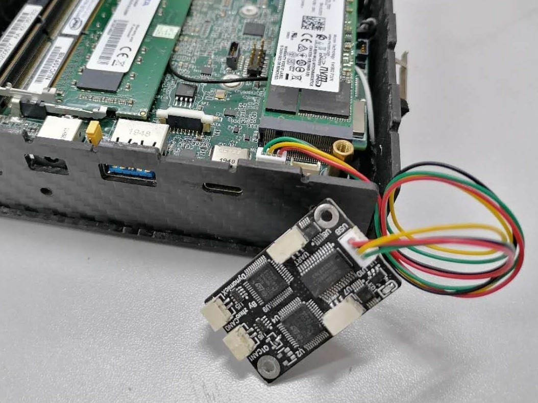
The purpose of this project is to provide Intel® NUC and other x86 device with a CAN (Controller Area Network) peripheral interface. Since NUC and most x86 device does not have simple peripheral interfaces such as SPI (Serial Peripheral Interface), it is impossible to use SPI to can chips such as MCP2515. Therefore, the project is developed based on the open source solution candleLight on GitHub, and STM32F072CBT6 is used as the main control chip to realize the function of USB (Universal Serial Bus) to can. STM32F072CBT6 has USB full speed peripherals and can peripherals that can work at the same time. It is packaged as QFP64 (Quad Flat Package) and is an excellent solution.The following figure shows the physical connection between Intel NUC and usb2can.
- EDA Tool: Altium Designer 20.0.13
- Compiler: gcc-arm-none-eabi 8-2019-q3-update
- Programming Tool: STM32CubeProgrammer v2.6.0
- bom: three different versions of usb2can material forms.
- candlelight: the repository of GitHub's open source solution candleLight.
- circuit: circuit schematic diagram and PCB source file designed with Altium designer.
- gerber: three different versions of usb2can manufacturing documents.
- image: picture in readme.
- firmware.bin: Compiled program binaries.
Note: the PCB and schematic diagram under the circuit folder are example circuits, which are directly used to manufacture products with production results other than those shown in the figure. If you want to directly reproduce the graphic version, please use the production file under the gerber folder.
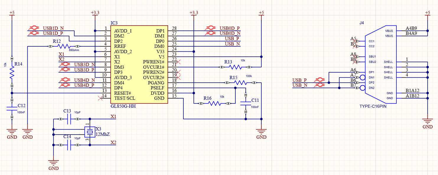
USB HUB Circuit Design: since the whole vehicle needs at least two can buses to ensure the integrity of the data packet returned by the motor, we use GL850G as the USB HUB chip to realize the scheme of USB one driving four. In addition, we also use Schmidt trigger to realize the power on sequence to ensure that the enumeration sequence of USB devices is consistent after each power on.
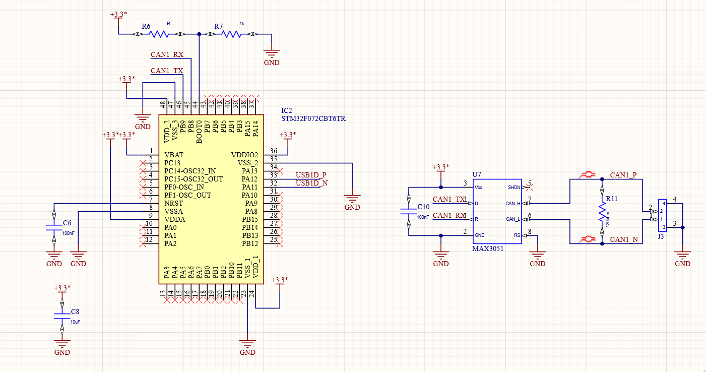
USB To CAN Circuit Design: use STM32F072CBT6 to realize the function of USB to can. The can level conversion chip adopts MAX3051EKA chip, which uses 3.3V power supply and is packaged as SOT23-8 (Small Outline Transistor), which provides the basis for PCB miniaturization. The purpose of R6 and R7 resistors in the figure is to change the boot mode of STM32, so that STM32 can switch between DFU (Device Firmware Upgrade) burning mode and flash mode by changing the short circuit mode of R6 and R7, so as to facilitate firmware burning.
- All USB buses need to be set as differential pairs, and the wiring rules of differential signals shall be strictly followed during wiring.
- All CAN buses need to be set as differential pairs, and the wiring rules of differential signals shall be strictly followed during wiring.
- The bottom of crystal oscillator and resonant capacitor should be hollowed out without copper.
- The power line width shall be greater than 0.3mm as far as possible to ensure that the power track does not collapse.
We provide three different versions of Gerber files for production: two-way CAN + UART + DBUS, four-way CAN, UART + DBUS.The circuits of these three versions are designed with two-layer PCB, with an area of about 20 * 30MM. You can directly submit the packaged Gerber file to a manufacturer (such as jlc) for production.
You can find the BOM (Bill Of Material) table corresponding to the board here and weld the components to the fabricated PCB according to this table. After welding, please carefully check whether there is residual solder between the pins, which will lead to short circuit of the circuit board. At the same time, you should also check whether there is false soldering of the pins.
After welding, use a multimeter to check whether there is a short circuit between 5V power interface and GND, and whether there is a short circuit between 3.3V power output and GND. When the above situation does not occur, connect the board to the USB port of the computer. At this time, you should see that the power indicator on the board is on, and the computer can recognize the USB HUB chip.
Note: do not weld the up / down resistance used to switch STM32 download mode at the same time, as it may cause a short circuit between the power supply and GND!
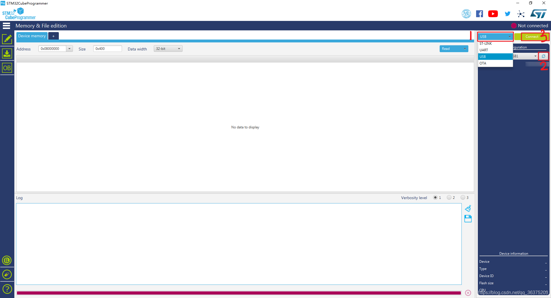
You can click here to download the compiled firmware, or follow the candlelight documentation to compile firmware by yourself. Finally, you will get the .bin file. We use STM32CubeProgrammer to burn the firmware into STM32 through USB. The steps to download firmware are shown below:
- Remove the pull-down resistance of BOOT0 pin of STM32 and weld the pull-up resistance.
- Connect the board to the USB port of the computer and open STM32CubeProgrammer.
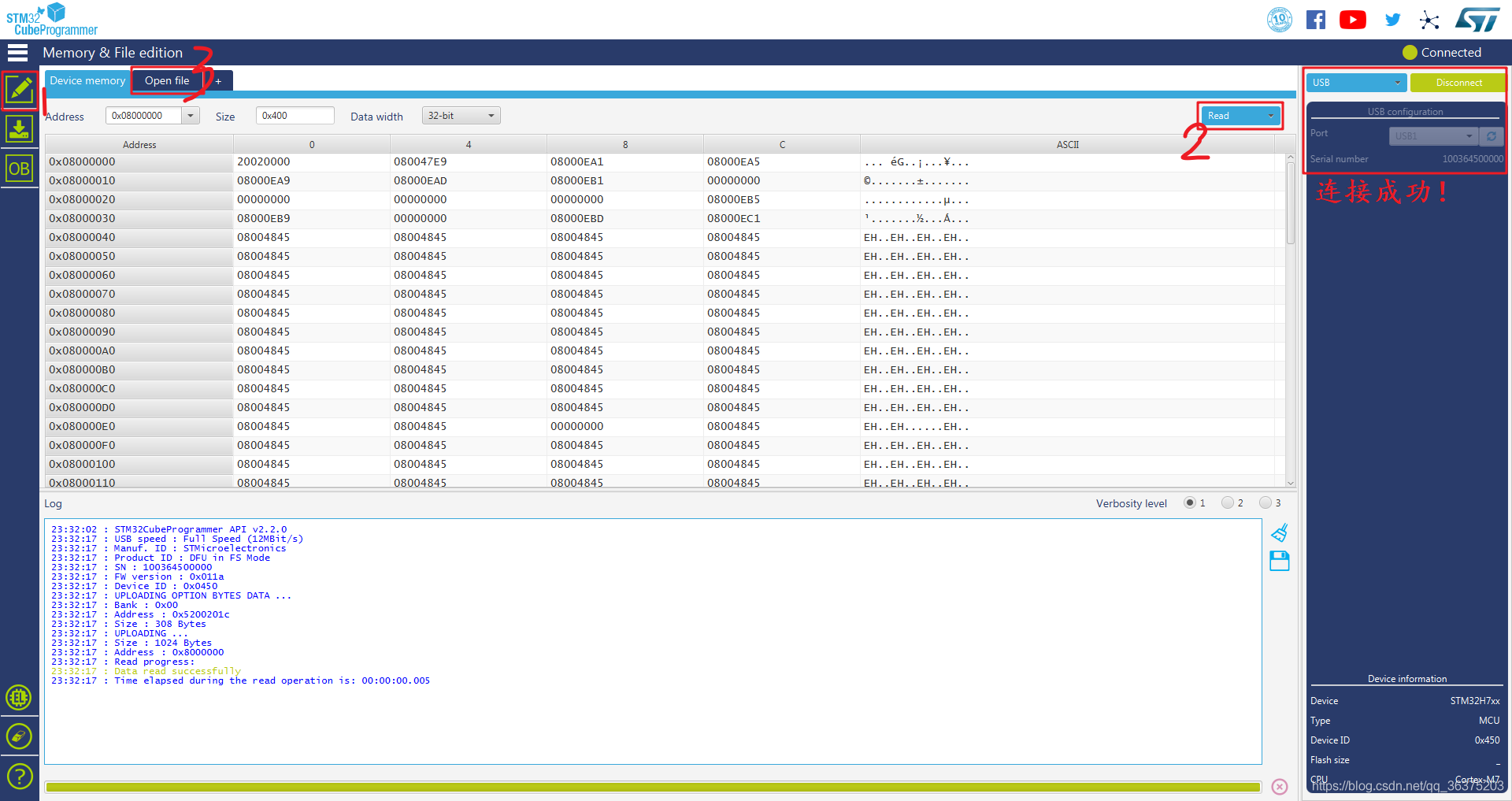
- Click the three buttons shown in the following figure in STM32CubeProgrammer to search for available STM32 devices.
- After successful connection, click the "Read" button to read the firmware and select the prepared firmware.
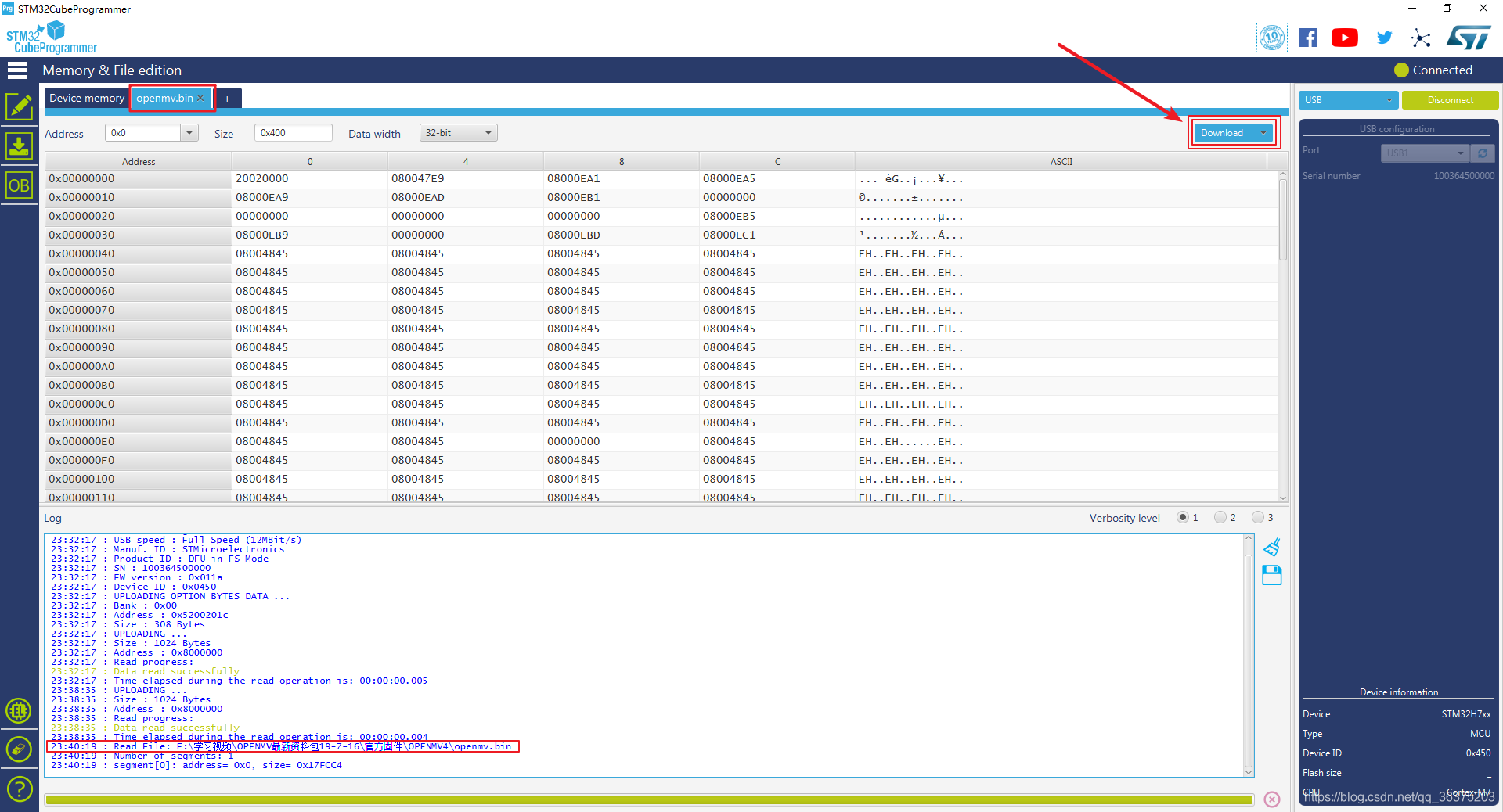
- Click "Download" to download the firmware. After the download is successful, you can see the successful information.
- Remove the pull-up resistance of BOOT0 pin on STM32 and weld the pull-down resistance. Power on again at this time, and the firmware will start running on STM32.
- Install dependent packages:
$ sudo apt-get update && sudo apt-get -y upgrade
$ sudo apt-get install -y can-utils net-tools- Check whether can device is detected:
$ ifconfig -a
# If a device with can name is found in the list, it means that the device can be recognized- Connect the two can ports with a straight line to facilitate loop back test.
- Initialize CAN0 and CAN1 devices with a bit rate of 1Mbits:
$ sudo ip link set can0 up type can bitrate 1000000
$ sudo ip link set can1 up type can bitrate 1000000- Open a new terminal to monitor the information received by can0:
$ candump can0- Sending information using can1 in a terminal:
$ cansend can1 200#5A5A5A5A5A5A5A5AIf you can see the following information from can1 in the terminal monitoring can0, it indicates that the communication is successful and the module works normally.
can0 200 [8] 5A 5A 5A 5A 5A 5A 5A 5AThe source code is released under a MIT License.
Affiliation:DynamicX
Maintainer:YanzhenZhu, 2208213223@qq.com
The product has been tested under Ubuntu 18.04 and 20.04. This is research code, expect that it changes often and any fitness for a particular purpose is disclaimed.