The Metriful MS430 is a low power, high accuracy, smart sensor cluster for indoor environment monitoring. It operates via a simple I2C-compatible interface and measures eighteen variables including air quality, light and sound levels.
This repository provides instructions and software examples for running the MS430 with Raspberry Pi (0/2/3/4/Pico), Arduino, ESP8266 and ESP32 host systems.
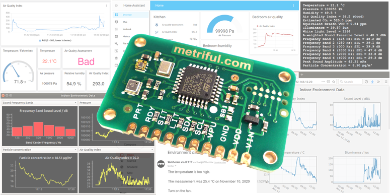
Code examples include interfaces to IFTTT, Home Assistant, ESPHome and IoT cloud platforms, as well as real-time graph software, web servers and interrupt detection.
This readme provides a quick-start guide to running the examples on various host systems.
The User Guide explains more about what the device measures.
The Datasheet is a detailed specification of the electrical and communications interfaces of the MS430.
- Handling precautions
- Arduino Nano 33 IoT, MKR WiFi 1010, Uno, Nano
- Raspberry Pi 0/2/3/4
- Raspberry Pi Pico
- ESP8266
- ESP32
- Particle sensor
- IoT cloud setup
- Graph web server
- IFTTT example
- ESPHome for Home Assistant
- Home Assistant POST example
- Graph viewer software
- Fahrenheit temperatures
The MS430 can be damaged by static electricity discharges. Minimize this risk by observing the following precautions:
- Handle the board by the edges
- Avoid touching any metal part of the device or circuit it connects to
- Store in the provided antistatic bag when not connected in a circuit
- Keep away from metal objects which could cause shorted connections
All code examples in the Arduino folder run on the Arduino Nano 33 IoT and Arduino MKR WiFi 1010, while those not requiring a network connection also run on Arduino Uno and Nano.
Note that steps 1 and 2 are already complete if you have used Arduino before on your computer.
- Download and install the Arduino IDE on your computer.
- Start the Arduino IDE for the first time. This will create a folder named Arduino/libraries in your user area (e.g. in the Documents folder on Windows computers).
- Clone, or download and unzip, the Sensor repository. From this, copy the folder Metriful_Sensor (located within the Arduino folder) into the Arduino libraries folder in your user area. Remove any previous version you may have. The rest of the downloaded repository can be placed anywhere e.g. in your documents folder.
If using Arduino Nano 33 IoT or Arduino MKR WiFi 1010, also do the following:
- Download and install the SAMD board package: in the Arduino IDE menu, go to Tools > Board > Boards Manager. Search for and install Arduino SAMD Boards (32-bits ARM Cortex-M0+)
- Install the WiFiNINA package: in the Arduino IDE menu, go to Tools > Manage Libraries. Search for and install WiFiNINA.
| MS430 pin | Uno | Nano | Nano 33 IoT | MKR WiFi 1010 |
|---|---|---|---|---|
| VIN | 5V | 5V | - | - |
| VDD | - | - | 3.3V | VCC |
| GND | GND | GND | GND | GND |
| VPU | IOREF | 5V | 3.3V | VCC |
| SCL | SCL | A5 | A5 | SCL |
| SDA | SDA | A4 | A4 | SDA |
| LIT | D4 | D4 | A1 | D4 |
| SIT | D7 | D7 | A2 | D5 |
| RDY | D2 | D2 | D11 | D0 |
- MS430 pin VDD is not used with the 5V systems (Uno and Nano) and pin VIN is not used with the 3.3V systems (Nano 33 IoT and MKR WiFi 1010).
- LIT/SIT connections are optional and only required if you are using light/sound interrupt outputs.
- VPU can be supplied from any spare host digital output pin set to a high voltage state. This can be useful for hosts without enough power output pins.
- Wire the MS430 board to the Arduino as described in the previous section.
- Plug the Arduino into your computer via USB.
- Start the Arduino IDE and open the chosen example code file, e.g. simple_read_sound.ino
- In the Arduino IDE menu, go to Tools > Board and select the Arduino model (Uno / Nano / Nano 33 IoT / MKR WiFi 1010).
- Go to Tools > Port and select the port with the Arduino attached.
- Select Sketch > Upload and wait for upload confirmation.
- Go to Tools > Serial Monitor to view the output (ensure 9600 baud is selected in the monitor).
The example programs for Raspberry Pi computers use Python 3 and are located in the Python/Raspberry_Pi folder.
This setup assumes that you are using Raspberry Pi OS. The standard OS version comes with all required Python packages already installed (except packages for the Graph viewer software). The Lite (command line) OS version requires package installation, as listed below.
-
If you are using Raspberry Pi OS Lite (or get missing package errors), run the following commands to install required packages:
sudo apt-get update sudo apt install i2c-tools python3-smbus python3-rpi.gpio pip3 install jinja2 psutil pyserial requests -
If you are using the "Bookworm" (or newer) version of Raspberry Pi OS, you need to upgrade your GPIO library by running the following:
sudo apt remove python3-rpi.gpio sudo apt update sudo apt install python3-rpi-lgpio -
Enable I2C on your Raspberry Pi using the raspi-config utility by opening a terminal and running:
sudo raspi-configSelect Interface Options and then I2C. A prompt will appear asking "Would you like the ARM I2C interface to be enabled?": select Yes and then exit the utility.
-
Shut-down the Raspberry Pi and disconnect the power. Wire up the hardware as described in the following section. Double-check the wiring then restart the Pi.
-
Check that the Metriful MS430 board can be detected by running:
sudo i2cdetect -y 1This should report the 7-bit address number 71.
-
Clone, or download and unzip, the Sensor repository, placing the folder anywhere on your system e.g. in your user home folder. The Raspberry Pi examples are in the Python/Raspberry_Pi folder.
| MS430 pin | Raspberry Pi pin number | Raspberry Pi pin name |
|---|---|---|
| VIN | - | - |
| VDD | 1 | 3V3 power |
| GND | 6 | Ground |
| VPU | 17 | 3V3 power |
| SCL | 5 | GPIO 3 (SCL) |
| SDA | 3 | GPIO 2 (SDA) |
| LIT | 7 | GPIO 4 |
| SIT | 8 | GPIO 14 |
| RDY | 11 | GPIO 17 |
- Raspberry Pi pin numbering is shown here.
- MS430 pin VIN is not used.
- LIT/SIT connections are optional and only required if you are using light/sound interrupts.
- Wire the MS430 to the Pi as described in the previous section.
- Open a terminal and navigate to the code examples folder Python/Raspberry_Pi.
- Run the example programs using Python 3, for example:
python3 simple_read_sound.py
All code examples in the Arduino folder work with the official Raspberry Pi Pico W and all non-WiFi examples work with the non-wireless Pico version.
Note that steps 1 and 2 are already complete if you have used Arduino IDE before on your computer.
- Download and install the Arduino IDE on your computer.
- Start the Arduino IDE for the first time. This will create a folder named Arduino/libraries in your user area (e.g. in the Documents folder on Windows computers).
- Clone, or download and unzip, the Sensor repository. From this, copy the folder Metriful_Sensor (located within the Arduino folder) into the Arduino libraries folder in your user area. Remove any previous version you may have. The rest of the downloaded repository can be placed anywhere e.g. in your documents folder.
- In the Arduino IDE menu, go to File > Preferences. In the box labeled "Additional Boards Manager URLs", paste the following link on a new line:
https://github.com/earlephilhower/arduino-pico/releases/download/global/package_rp2040_index.json - In the Arduino IDE menu, go to Tools > Board > Boards Manager. Search for and install the package named Raspberry Pi Pico/RP2040 by Earle F. Philhower.
| MS430 pin | Pico pin number |
|---|---|
| VIN | - |
| VDD | 36 |
| GND | 23 |
| VPU | 36 |
| SCL | 27 |
| SDA | 26 |
| LIT | 31 |
| SIT | 32 |
| RDY | 34 |
- The pin numbering is shown on the official pinout datasheet available at https://datasheets.raspberrypi.com.
- MS430 pin VIN is not used.
- LIT/SIT connections are optional and only required if you are using light/sound interrupts.
- VPU can be supplied from any spare host digital output pin set to a high voltage state. This can be useful for hosts without enough power output pins.
- Wire the MS430 board to the Pico as described in the previous section.
- Plug the Pico board into your computer via USB.
- Start the Arduino IDE and open the chosen example code file, e.g. simple_read_sound.ino
- In the Arduino IDE menu, go to Tools > Board and select "Raspberry Pi Pico W" or "Raspberry Pi Pico" as appropriate.
- Go to Tools > Port and select the port with the Pico attached.
- Select Sketch > Upload and wait for upload confirmation.
- Go to Tools > Serial Monitor to view the output (ensure 9600 baud is selected in the monitor).
All code examples in the Arduino folder have been tested on NodeMCU and Wemos D1 Mini, and are programmed using the Arduino IDE.
Other ESP8266 development boards should also work but may use a different pinout and may therefore require edits to the host_pin_definitions.h file.
Note that steps 1 and 2 are already complete if you have used Arduino IDE before on your computer.
- Download and install the Arduino IDE on your computer.
- Start the Arduino IDE for the first time. This will create a folder named Arduino/libraries in your user area (e.g. in the Documents folder on Windows computers).
- Clone, or download and unzip, the Sensor repository. From this, copy the folder Metriful_Sensor (located within the Arduino folder) into the Arduino libraries folder in your user area. Remove any previous version you may have. The rest of the downloaded repository can be placed anywhere e.g. in your documents folder.
- In the Arduino IDE menu, go to File > Preferences. In the box labeled "Additional Boards Manager URLs", paste the following link on a new line:
https://arduino.esp8266.com/stable/package_esp8266com_index.json - In the Arduino IDE menu, go to Tools > Board > Boards Manager. Search for and install the package named esp8266 by ESP8266 Community.
| MS430 pin | ESP8266 |
|---|---|
| VIN | - |
| VDD | 3V3 |
| GND | GND |
| VPU | 3V3 |
| SCL | D1 (GPIO 5) |
| SDA | D2 (GPIO 4) |
| LIT | D3 (GPIO 0) |
| SIT | D5 (GPIO 14) |
| RDY | D6 (GPIO 12) |
- The D pin numbers refer to the usual pin labels printed on the development board. The GPIO numbers are the actual ESP8266 I/O identities.
- MS430 pin VIN is not used.
- LIT/SIT connections are optional and only required if you are using light/sound interrupts.
- VPU can be supplied from any spare host digital output pin set to a high voltage state. This can be useful for hosts without enough power output pins.
- Wire the MS430 board to the ESP8266 as described in the previous section.
- Plug the ESP8266 board into your computer via USB.
- Start the Arduino IDE and open the chosen example code file, e.g. simple_read_sound.ino
- In the Arduino IDE menu, go to Tools > Board and select your development board, or "Generic ESP8266 Module", or experiment until you find one that works.
- Go to Tools > Port and select the port with the ESP8266 attached.
- Select Sketch > Upload and wait for upload confirmation.
- Go to Tools > Serial Monitor to view the output (ensure 9600 baud is selected in the monitor).
All code examples in the Arduino folder have been tested on DOIT DevKit v1, and are programmed using the Arduino IDE.
Other ESP32 development boards should also work but may use a different pinout and may therefore require edits to the host_pin_definitions.h file.
Note that steps 1 and 2 are already complete if you have used Arduino IDE before on your computer.
- Download and install the Arduino IDE on your computer.
- Start the Arduino IDE for the first time. This will create a folder named Arduino/libraries in your user area (e.g. in the Documents folder on Windows computers).
- Clone, or download and unzip, the Sensor repository. From this, copy the folder Metriful_Sensor (located within the Arduino folder) into the Arduino libraries folder in your user area. Remove any previous version you may have. The rest of the downloaded repository can be placed anywhere e.g. in your documents folder.
- In the Arduino IDE menu, go to File > Preferences. In the box labeled "Additional Boards Manager URLs", paste the following link on a new line:
https://espressif.github.io/arduino-esp32/package_esp32_index.json - In the Arduino IDE menu, go to Tools > Board > Boards Manager. Search for and install the package named esp32 by Espressif Systems then restart the IDE.
| MS430 pin | ESP32 |
|---|---|
| VIN | - |
| VDD | 3V3 |
| GND | GND |
| VPU | 3V3 |
| SCL | D22 |
| SDA | D21 |
| LIT | D18 |
| SIT | D19 |
| RDY | D23 |
- MS430 pin VIN is not used.
- LIT/SIT connections are optional and only required if you are using light/sound interrupts.
- VPU can be supplied from any spare host digital output pin set to a high voltage state. This can be useful for hosts without enough power output pins.
- Wire the MS430 board to the ESP32 as described in the previous section.
- Plug the ESP32 board into your computer via USB.
- Start the Arduino IDE and open the chosen example code file, e.g. simple_read_sound.ino
- In the Arduino IDE menu, go to Tools > Board and select your development board, or experiment until you find one that works.
- Go to Tools > Port and select the port with the ESP32 attached.
- Select Sketch > Upload and wait for upload confirmation.
- Go to Tools > Serial Monitor to view the output (ensure 9600 baud is selected in the monitor).
The MS430 is compatible with two widely-available air particle sensors: the Shinyei PPD42 and the Nova SDS011. The particle sensor is optional and only a single sensor can be connected at any time. The PPD42 is not recommended and is supported for backwards compatibility only.
Both sensor models require three wire connections: 5V, GND, PRT and a small edit to the example code.
| PPD42 pin number | SDS011 pin label | |
|---|---|---|
| 5V | 3 | 5V |
| GND | 1 | GND |
| PRT | 4 | 25um |
- PRT is on the MS430 board
- 5V and GND are supplied by the host system, or from a separate power supply. If using a separate power supply, the power supply GND must be connected to host GND.
- The SDS011 pin labeled "25um" is the data output for 0.3 - 10 µm particles.
5V is available from the hosts when they are powered from a USB power supply:
| Host device | 5V pin name/number |
|---|---|
| Raspberry Pi 0/2/3/4 | Pin 2 |
| Raspberry Pi Pico | Pin 40 |
| Arduino Uno | 5V or IOREF (*) |
| Arduino Nano | 5V |
| Arduino Nano 33 IoT | VUSB (**) |
| Arduino MKR WiFi 1010 | 5V |
| ESP8266 | 5V or Vin or VU |
| ESP32 | VIN |
(*) To obtain a third 5V output from the Uno: use pin number 2 on the 6-pin ICSP header
(**) To obtain 5V output on the Nano 33 IoT: the solder bridge labeled "VUSB" on the underside of the Arduino must be soldered closed, then use the VUSB pin.
- Raspberry Pi 0/2/3/4: pin 9 can be used as an extra GND connection.
- Raspberry Pi Pico: pins 3, 8, 13, 18, 28, 33, 38 can be used as extra GND connections.
- Pin labels for ESP8266 and ESP32 may be different on some boards
-
Arduino: in Metriful_sensor.h on the line:
#define PARTICLE_SENSOR PARTICLE_SENSOR_OFFchange
PARTICLE_SENSOR_OFFto be eitherPARTICLE_SENSOR_PPD42orPARTICLE_SENSOR_SDS011 -
Raspberry Pi: in /sensor_package/sensor_functions.py on the line:
PARTICLE_SENSOR = PARTICLE_SENSOR_OFFchange
PARTICLE_SENSOR_OFFto be eitherPARTICLE_SENSOR_PPD42orPARTICLE_SENSOR_SDS011
The IoT_cloud_logging code example shows how to send data to an Internet of Things (IoT) cloud storage account. It can be used with Arduino Nano 33 IoT, MKR WiFi 1010, ESP8266, ESP32 and Raspberry Pi host systems.
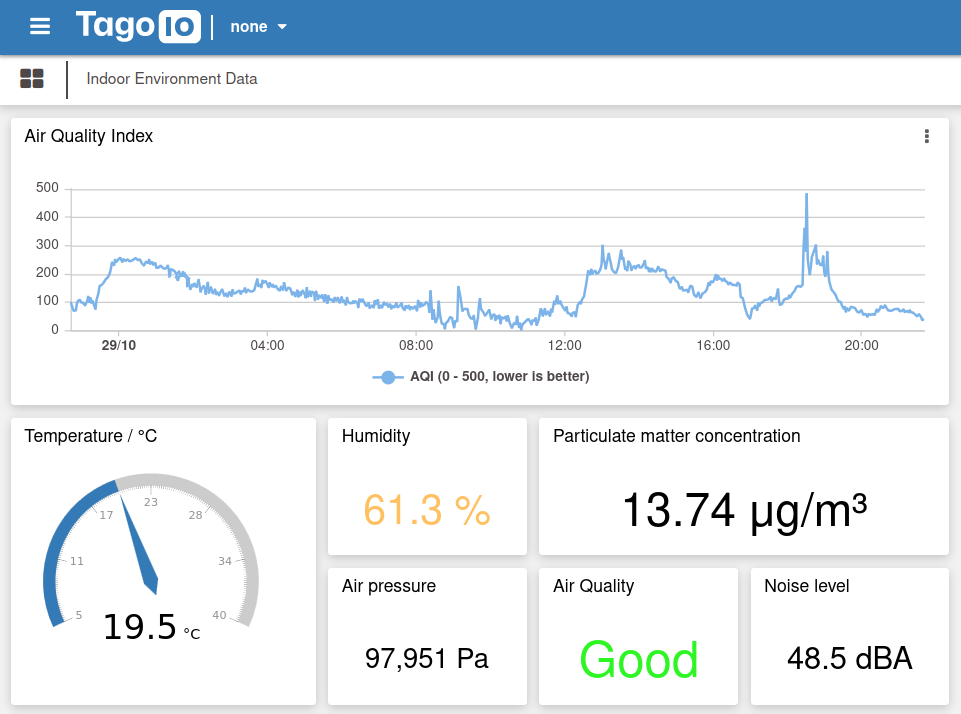
IoT cloud hosting is available from many providers around the world. Some offer free accounts (with storage or access limits) for non-commercial purposes. The IoT cloud logging example gives a choice of two providers, Tago.io and Thingspeak.com. The following sections give a brief overview of how to set up free accounts with these providers: for further information see the relevant provider website.
The steps required to set up Tago for the IoT cloud logging code example are:
- Register for a free account at Tago.io
- In the Devices menu, click Add Device.
- Select Custom HTTPS (HTTP) as the device type.
- Choose a device name (e.g. Indoor Environment Monitor) and click Create device
- On the General Information tab of the new device, in the section Token & Serial Number, click the eye icon to reveal the token (a long sequence of letters, numbers and hyphens). Copy this token.
- Paste the token into the IoT_cloud_logging example code as the variable TAGO_DEVICE_TOKEN_STRING and set the variable useTagoCloud as true.
- Run the IoT cloud logging example code on the internet-connected host for a few minutes to ensure at least one set of data has been logged.
- Verify that data are being stored in the Tago cloud by viewing the bucket’s Variables tab. This should show the following short names for the environment data variables:
- temperature
- pressure
- humidity
- aqi (air quality index, AQI)
- aqi_string (a text interpretation of the AQI)
- bvoc (equivalent breath VOC concentration)
- spl (the A-weighted Sound Pressure Level)
- peak_amp (the peak sound amplitude)
- illuminance
- particulates (air particle concentration)
- Create a Tago dashboard for viewing the data: click the + to add a new dashboard, choose its name and click save.
- Add widgets of various types to the dashboard (e.g. Line for a simple graph, Card to display text or numbers).
- Configure each widget: the minimum configuration is to choose the Variable which it displays. It is also possible to edit graph and axis titles, coloring, calculate formulas, etc.
- Set graph displayed time period, e.g. for 24 hours: on the Data Range & Format tab of the chart settings, input 864 as the maximum number of points to be displayed. This assumes that the data are logged every 100 seconds (there are 86,400 seconds in 24 hours).
- Create a public link for sharing your dashboard: click the three dots next to your dashboard name on the left-hand list. Choose “share” then copy the link displayed under the “share public” tab.
The steps required to set up Thingspeak for the IoT cloud logging code example are:
- Register for a free account at Thingspeak.com
- On the My Channels page, click the New Channel button
- Choose a channel name (e.g. Indoor Environment Data)
- Enable all eight fields (check boxes)
- Put the following labels in the field name boxes (the order is important):
- Field 1: Temperature / C
- Field 2: Pressure / Pa
- Field 3: Humidity / %
- Field 4: Air Quality Index
- Field 5: Breath VOC / ppm
- Field 6: Sound Level / dBA SPL
- Field 7: Illuminance / lx
- Field 8: Particle Concentration
- Click Save Channel. The channel will show eight (initially empty) graphs.
- To set graph time periods to 24 hours: on each graph click the pencil icon, delete 60 from the Results box and put 1 in the Days box, then click Save. This changes the graph period from the last 60 values to the last 1 day. This must be done separately for both the private and public view if the channel is shared publicly.
- The channel can be made public, if desired, from the Thingspeak Sharing tab.
- Go to the API Keys tab and copy the Write API Key (a sequence of letters and numbers).
- Paste the API key into the Metriful IoT cloud logging example code as the variable THINGSPEAK_API_KEY_STRING and set the variable useTagoCloud as false.
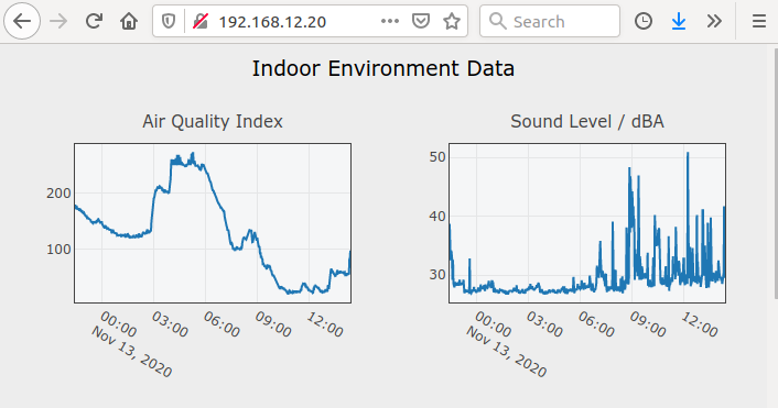
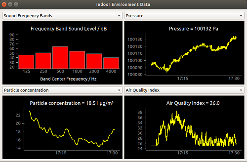
The graph_web_server example produces a web page with a set of graphs which display data stored on the host. The page can be accessed from other devices on your home network using their internet browsers. This is a good local alternative to using a cloud IoT service.
When opened in a browser, the web page will attempt to run the Plotly javascript library which is used to create the graphs. If there is no internet access, the browser may be able to use a cached copy if it previously accessed the page with internet access. Otherwise, the graphs will not load and you will only see text data.
A button on the web page allows you to download the stored data as a CSV (comma separated value) text file, which can be opened with many spreadsheet applications.
The IFTTT example shows how to send data to IFTTT.com, which will trigger an email alert. It is compatible with IFTTT's free account.
The host device monitors some of the environment data and sends the alert when the values go outside your chosen "safe" range. The emails you receive will look like:
The temperature is too high.
The measurement was 25.5 °C on October 10, 2020 at 05.54PM.
Turn on the fan.
You can customize all parts of this message.
- Go to IFTTT.com and sign up for a free account.
- Click Create to start a new applet.
- Click If This (Add), search for service Webhooks and click Receive a web request, then Connect.
- Enter an event name, e.g. alert_event, then click Create trigger.
- Click Then That (Add) and search for email.
- Choose either Email to get a new email for every alert, or choose Email Digest to get ONE email per day/week which contains all alerts. Then click Connect.
- Enter and validate your email address when prompted.
- Enter a Title/Subject for the emails, e.g. Environment data alert.
- Delete all text from the Body/Message text box and paste in the following:
{{Value1}}<br><br> {{Value2}} on {{OccurredAt}}<br><br> {{Value3}} - Click Create action, then Continue, then Finish to complete the applet setup.
- Go to your IFTTT Home page and click on the applet you just created.
- Click the triangle Webhooks icon, then on Documentation.
- Copy the key (letter number sequence) that is displayed.
- Edit the IFTTT example code file, pasting in this key and the event name (from step 4).
- Run the program.
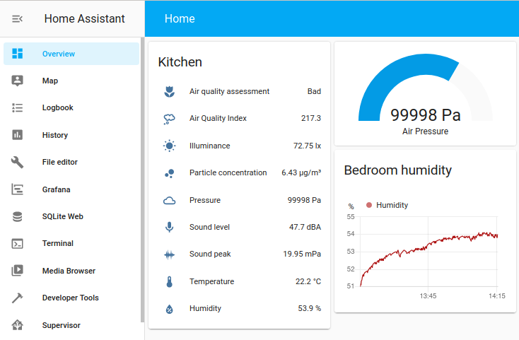
Send sensor data to an installation of Home Assistant using the ESPHome system.
Your microcontroller device must be one of: ESP8266, ESP32, Raspberry Pi Pico W. Other devices (Arduino or Raspberry Pi 0/2/3/4) must use the Home Assistant POST method instead.
These instructions assume that you already have a working Home Assistant installation. All of the steps are done from your personal computer, not the Home Assistant server computer.
-
Install ESPHome on your computer.
-
In the Arduino/Metriful_Sensor folder, run terminal command:
esphome dashboard .(note the dot). This starts a temporary local web server on your computer. Leave this process running. -
Go to http://0.0.0.0:6052 or http://127.0.0.1:6052 in a browser to view the temporary ESPHome dashboard. Click "new device", ignore any note about HTTPS, and click "continue".
-
In the dialog, give your device a unique name (this is the device_name) and input your WiFi network name (SSID) and password.
-
Choose your board type from the list (ESP, Pico, etc.), then copy the encryption key for later use (it can also be found in the generated yaml file).
-
Plug the microcontroller board into your computer via USB, then click "install" and choose:
- Manual download for Raspberry Pi Pico W; install is complete when the drive disappears.
- Plug into the computer running ESPHome for all other boards. The install is complete when coloured logs about WiFi signal appear in the window: then click "stop" to close the window.
-
In the Arduino/Metriful_Sensor folder, a new file called <device_name>.yaml should have appeared. As its first three lines, it has:
esphome:
  name: <device_name>
  friendly_name: <device_name>
Where <device_name> is the name you chose. Replace these three lines with the entire contents of Arduino/Metriful_sensor/ESPHome_patch.yaml copied and pasted.
-
In the substitutions section of the edited yaml file, provide your device_name and (optionally) values for the other two variables. Save the file.
-
A new tile should have appeared on the ESPHome dashboard web page, titled with your device_name. Click the 3 dots on it, then on "install" and choose "wirelessly". The install is complete when coloured logs about WiFi signal appear in the window: then click "stop" to close the window. Close the browser and stop the server process that began in step 2.
-
Go to your Home Assistant web dashboard. There may be a notification that a new device has been discovered. Click "configure" on it and enter the encryption key from step 5 (the key is also saved in <device_name>.yaml).
If you are not prompted about the device discovery: go to Settings > Devices & Services > Devices tab > "Add device". Search for ESPHome in the list, then for "Host" enter <device_name>.local where <device_name> is the name you chose.
-
In Home Assistant go to Settings > Devices & Services > Devices tab, click on the newly added device and click "add to dashboard" under its sensors list. The list of data variables appears as a card on the dashboard/overview page.
-
You can improve the appearance of the dashboard card, for example: edit the names/title, remove variables, reorder the list. You can also add data graphs, gauges, etc.
Send sensor data to an installation of Home Assistant using HTTP requests.
This code example is suitable for all supported MS430 hosts. If you are using ESP8266, ESP32 or Raspberry Pi Pico W, you can also use our ESPHome example.
These instructions assume that you already have a working Home Assistant installation.
- Edit the program file "Home_Assistant":
- Choose a sensor name and insert the IP address of the computer running Home Assistant.
- Generate a "long lived access token":
- On the Home Assistant web interface, click your username at the bottom left corner to go to your profile page.
- At the bottom of the profile page, under Long-Lived Access Tokens, click CREATE TOKEN and copy the very long sequence of numbers/letters.
- Paste the token into the program file.
- Run the program and wait a few minutes so that the first data have been sent.
- Check that data are being received by Home Assistant:
- Go to Settings > Devices & Services > Entities tab
- There should be a series of entries with names like SENSOR_NAME.temperature, SENSOR_NAME.air_quality_index, etc. Where SENSOR_NAME is the name you chose in the program file.
-
Add display cards to the Overview page dashboard - these can be text labels, gauges, graphs etc.
- Click the 3 dots at the top right corner and choose Edit Dashboard then + Add Card
- On the "By entity" tab, search for your chosen SENSOR_NAME and select one or more data variables
- Pick a display card, e.g. Entities, Gauge, or History graph
-
You can also view data graphs on the Home Assistant History page.
-
If Home Assistant is rebooted, cards will show Entity not available (and the sensor will disappear from the entity list) until a new value is received. The data history will also reappear when this happens.
This simple example shows how to generate a notification when the temperature goes above 22 °C. Much more advanced triggers and actions can be configured.
- Go to Settings > Automations & Scenes
- Click + create automation to create a new automation
- On the "New Automation" page, click the 3 dots at the top right corner and choose Edit in YAML
- Delete everything in the text box and replace with:
Replace kitchen3 with your SENSOR_NAME chosen name and the other fields with your own values.
trigger: - platform: numeric_state entity_id: kitchen3.temperature above: '22' action: - service: persistent_notification.create data: title: Kitchen temperature too high message: 'The temperature is {{ states.kitchen3.temperature.state_with_unit }}' - Click the save icon to finish.
- Optional: click run to test it (the action is forced to run without the trigger condition).
The graph viewer uses a graphical interface to show environment data updating in real-time. It uses Python and runs on all major operating systems.
Note that the graph viewer does not run on Raspberry Pi OS Lite because there is no desktop interface.
There are two versions provided in the Python folder:
-
graph_viewer_I2C.py
Runs only on Raspberry Pi 0/2/3/4 and communicates directly with the MS430 board which is connected to the Pi GPIO pins.
-
graph_viewer_serial.py
Runs on multiple operating systems (windows, linux, mac) and uses serial over USB to get data from the MS430 sensor via a microcontroller board (e.g. Arduino, ESP8266, Raspberry Pi Pico etc).
This assumes you have already installed Python3 and Pip3.
Windows
pip3 install pyqtgraph pyqt5 pyserial
Linux, including Raspberry Pi
sudo apt install python3-pyqt5 libatlas-base-dev libopenblas-dev
pip3 install pyqtgraph pyserial
Also on Raspberry Pi: you will need to complete the first time Raspberry Pi setup if not already done.
Extra steps for some Linux versions e.g. Ubuntu
- If not already present, install pip3 by enabling the "Universe" software repository, then
sudo apt install python3-pip - Add the user to the dialout group for permission to use the serial port.
- Follow the usual hardware setup for Raspberry Pi and check that the MS430 board is recognized by the Pi.
- Run the program with:
python3 graph_viewer_I2C.py
- Follow the usual hardware setup for your microcontroller board.
- Program the microcontroller board with either cycle_readout.ino or on_demand_readout.ino, with parameter
printDataAsColumns = trueand a cycle period of 3 seconds (or less). - Connect the microcontroller USB cable to your computer and close all serial monitor software.
- Edit the Python code file so that the particle sensor and temperature unit settings match those used on the microcontroller.
- Put the serial port name (system dependent, e.g. COM1) in the serial_port_name parameter in the code file.
- Run the program with:
python3 graph_viewer_serial.py
The temperature is always measured by the MS430 as a Celsius value. The software output values (printed to screen/file, or sent over the network, etc) are by default in Celsius but will be converted to Fahrenheit if the following changes are made:
-
On Raspberry Pi
In file sensor_functions.py set the following:
USE_FAHRENHEIT = True -
On Arduino
In file Metriful_sensor.h un-comment the following line:
#define USE_FAHRENHEIT
The following versions were used for testing.
- Arduino IDE: 2.3.4
- Raspberry Pi Pico/RP2040 by Earle F. Philhower board package: 3.6.0
- ESP32 by Espressif Systems board package: 2.0.14
- ESP8266 by ESP8266 Community board package: 3.1.2
- Arduino SAMD board package: 1.8.13
- WiFiNINA library: 1.8.14
- Raspberry Pi OS: 11 (bullseye)
- i2c-tools: 4.2-1+b1
- python3-smbus: 4.2-1+b1
- python3-rpi.gpio: 0.7.0-0.2+b1
- Python version: 3.9.2
- Jinja2: 2.11.3
- psutil: 5.8.0
- PyQt5: 5.15.2
- pyqtgraph: 0.13.3
- pyserial: 3.5b0
- requests: 2.25.1
- Home Assistant OS: 15.0 (RPi 3)
- ESPHome: 2025.2.2
The simplest arrangement is to leave the sensor board open to the air. Use bolts, PCB spacers/standoffs, adhesive foam pads, or hot glue to fix the board to a stand (e.g. a 6x4" picture frame). Wires can be hidden around the back to make it neater.
You can use a box or case with small holes for air and sound entry. Light entry can be through a transparent or open window hole.
A smoke alarm with the electronics removed makes an ideal, inexpensive case. Ensure that this cannot be mistaken for a functioning smoke alarm for safety reasons.
The following tips may also help:
-
Fix the board as close as possible to the box wall but without having the sensors touching the wall.
-
Minimize the total air volume inside the box, so it exchanges quickly.
-
Provide some holes for air and sound entry – these do not have definite requirements.
-
If you use a particle sensor, its entry and exit ports need to be unobstructed and open to the surrounding air. So mount it against the box wall, with its ports lined up against holes in the box.
-
The light sensor requires a minimum hole size to have the correct exposure, with the diameter depending on sensor distance from the hole. For example, having the sensor 2 mm from the casing edge requires a hole of about 6 mm diameter. More of these values are given on page 18 of this document: https://www.vishay.com/docs/84367/designingveml6030.pdf
-
The host releases heat which can affect the temperature reading if they are both together in the same box. If you get a small temperature offset, you can measure it with an accurate thermometer and subtract it in the software - this is what the sensor manufacturer recommends.
-
The SDS011 particle sensor has a powered fan which will affect the MS430 sound measurements. Reduce this by situating the SDS011 further away from the MS430, or with insulating material. Alternatively, you can "gate" power to the SDS011 to turn it on and off - the particle_sensor_toggle example and the User Guide give more information on this.
Having problems with the hardware or software? Please check TROUBLESHOOTING before opening a GitHub issue.
Changes, fixes and additions in each software release version are listed in the CHANGELOG
See the LICENSE file for software license rights and limitations (MIT).
This document and repository, and the products described herein, are subject to specific disclaimers set forth in the DISCLAIMER file.