Controller board for building servo-based robots, such as hexapods.
 Render of board rev 2
This project was designed to allow rapid prototyping of different types of servos and sensors for walking robots: it's easy to switch out different sensors, and I2C buses are exposed for adding standard plugin components, such as those from Adafruit. But the board could be used for any projects needing a lot of servos.
The main benefit of this over a standard Arduino is the number of PWM pins and the server sockets, plus the power supply monitoring circuitry.
You should be able to get a standard "spiderbot" Arduino sketch running on this hardware quite easily: I'll shortly publish some test sketches and controller firmware.
Have fun!
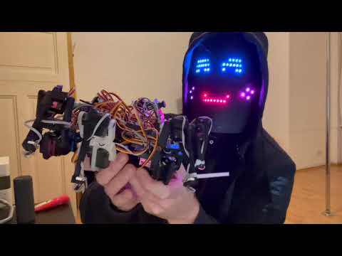
 Board in action
Core features:
- ESP32 processor, Arduino compatible
- 32 PWM servo channels (ie max 10 legs)
- 6 foot contact sensors
- 7.6v LiPo battery, or power supply input
- Power supply monitoring for:
- main battery voltage + current
- 3.3v regulated rail voltage
- 2x 5v rail servo voltages
With standard plugin modules installed in sockets:
- speech and audio output
- infrared beacon detection
- inertial measurement unit
- extra PWM channels
See it running here (video):
The ESP32 CAM module can run on 3.3v or 5v. If you are getting freezes and dropped frames from the camera, try running it from the robot's 5v rail instead of 3.3v.
The ESP32 CAM has a XC6206-2.8V regulator after its 3.3v regulator, and this component has a dropout voltage up to ~500mV according to the specs. My hypothesis is that the camera crashes on slight undervoltages.
So the 3.3v rail must be rock solid - this may not be the case with your regulator, so it's generally recommended to run the ESP32 CAM off the 5v rail. Even with many noisy servos, the camera works fine on the robot on the 5v rail.
Pullups can vary between 2K and 10K - if there are problems communicating with I2C, try reducing the pullups. Higher pull-ups waste less power.
Note that the main branch is a work in progress: please take an earlier revision if you want a working layout. These are tested and working (with some minor noise issues and a couple of bodge wires needed).
- main branch is a work in progress: I am upgrading to ESP32-S3 and have fixed some noise issues and minor annoyances. Use an older tag if you want something that works.
- 2nd revision: 32 PWM channels onboard, 6 foot switches + power pins for IR proximity sensors
- 1st revision: 16 PWM channels, 4 foot switches