Instruction Set
This processor uses a custom instruction set that it is optimized for highly parallel use cases, such as compute kernels. Unlike most modern processors, which have separate sets of vector and scalar arithmetic instructions, this uses a unified set of operations that can take vectors, scalars, or a mix of them as operands.
This architecture has 32 scalar registers and 32 vector registers. Vector registers have 16 elements (which we will refer to as 'lanes'). Each scalar register or vector lane is 32-bits wide and can contain a single precision floating point value or an integer. How they are interpreted is based on the instruction. Each hardware thread also has a 32-bit program counter register, but it is not directly accessible by software.
All instructions that take vectors support predication, which allows them to control which lanes of the vector the instruction updates. Compute kernels that use SIMD parallelism can be use this to support branch divergence, where vector lanes take different branches.
Instructions are 32-bit fixed length and must be four byte aligned in memory. There are four main instruction types: arithmetic, memory access, branch, and cache control, which the next sections describe in more detail.
Arithmetic instructions operate only on register values and do not support memory operands. An arithmetic instruction specifies a destination register and one or two source registers. For example, to add an integer in scalar register 2 to scalar register 3 and store the result in register 1:
add_i s1, s2, s3This architecture does not have separate integer and floating point register files. Depending on the operation, an instruction may treat register values as floating point values, two's complement signed integers, or unsigned integers. Floating point values use the IEEE 754 "binary32" format. Vector operations compute each of the 16 lanes independently. Vector registers have a 'v' prefix. This adds vector register 2 to 3 and puts the result in register 1:
add_i v1, v2, v3An instruction may mix scalar and vector registers. The scalar value is duplicated to all 16 lanes.
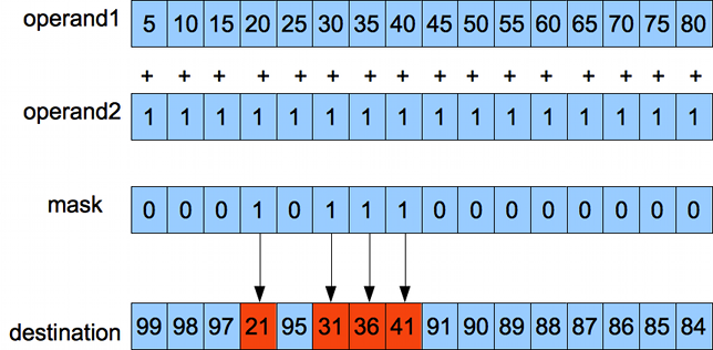
add_i v4, v5, s2A vector instruction may specify a mask register, which controls which lanes in the destination register it updates. When present, it is the second parameter in assembly form. It is one of the scalar registers.
add_i_mask v1, s2, v2, v3Each bit in the low 16 bits of the mask corresponds to one lane in the vector register. The least significant bit corresponds to lane 0. A one bit in the mask writes the value to the lane. A zero bit does not: the lane retains the old value. Lanes with a zero bit will also not generate any exceptions.
For example:
A vector comparison sets each bit in the low 16 bits of the destination corresponding to result of the comparison of the associated lanes, with the same format as a masked instruction. For example:
cmpgt_i s1, v1, v2Programs can use the results of comparisons as masks for parallel execution. For example, say we have this high level construct:
if (a > b)
   b = a - c
else
   a = b - c
The following runs 16 instances of this in parallel (with each vector lane representing a single instance of the program):
cmpgt_i    s1, v1, v2      # s1 stores the result of the comparison v1 > v2
mul_i_mask v3, s1, v2, v4  # The first part of if clause: only cases where compare is true
xor        s1, s1, -1      # Invert comparison
mul_i_mask v2, s1, v3, v5  # Else clause
This runs both clauses of the if construct, using masks to control which lanes it writes results to. Programs can nest conditionals by using multiple mask registers.
A scalar comparison sets the destination register to 0xffff if the comparison matches, 0 otherwise.

-
fmt - Describes operand types and mask usage. Using a format not in this list raises an invalid instruction fault.
Value
dest
src1
src2
Masked
000
Scalar
Scalar
Scalar
N
001
Vector
Vector
Scalar
N
010
Vector
Vector
Scalar
Y
100
Vector
Vector
Vector
N
101
Vector
Vector
Vector
Y
-
mask - When the fmt field indicates a mask is present, the processor fetches the value from this register. The low 16 bits of the register specify which lanes to update. A comparison instruction does not use a mask register.
-
dest - The instruction stores its result in this register. The 'fmt' field determines the type (vector or scalar), which is the same as op1 type, except for a comparison instruction. A comparison always has a scalar destination.
-
src1 - The instruction fetches a value from this register and uses it as the first source operand. The fmt field indicates whether this is a vector or scalar register.
-
src2 - The instruction fetches a value from this register and uses it as the second source operand. Unary operations use src2 as their operand.
-
opcode - Arithmetic operation. The implementation does not raise a fault if an instruction has an invalid opcode
Opcode
Mnemonic
Description
000000
or
Bitwise Logical Or
000001
and
Bitwise logical And
000010
syscall
Raise system call trap. 5
000011
xor
Bitwise logical exclusive or
000101
add_i
Integer addition
000110
sub_i
Integer subtraction
000111
mull_i
Low 32 bits of integer multiplication
001000
mulh_u
Upper 32 bits of unsigned integer multiplication
001001
ashr
Shift right (signed) 1
001010
shr
Shift right (unsigned) 1
001011
shl
Shift left 1
001100
clz
Count leading zeros 6 2
001101
shuffle
Shuffle vector elements. The second argument is a vector where each lane is an index into the first vector.
001110
ctz
Count trailing zeros 6 2
001111
move
Copy. Uses op2 as the result. Supports immediate and register transfers.
010000
cmpeq_i
Compare and set if integers equal
010001
cmpne_i
Integer not equal
010010
cmpgt_i
Integer greater (signed)
010011
cmpge_i
Integer greater or equal (signed)
010100
cmplt_i
Integer less than (signed)
010101
cmple_i
Integer less than or equal (signed)
010110
cmpgt_u
Integer greater
010111
cmpge_u
Integer greater or equal
011000
cmplt_u
Integer less than
011001
cmple_u
Integer less than or equal
011010
getlane
Copy vector lane into scalar register
011011
ftoi
Convert floating point value to signed integer 6
011100
reciprocal
Ra ~= 1.0 / rB. Floating point reciprocal estimate with 6 bits of precision. 6
011101
sext8
Sign extend an 8 bit value to 32 bits 6
011110
sext16
Sign extend a 16 bit value to 32 bits 6
011111
mulh_i
Upper 32 bits of integer multiplication, sign extended values
100000
add_f
Floating point add 3
100001
sub_f
Floating point subtract 3
100010
mul_f
Floating point multiply 3
101010
itof
Convert signed integer to floating point 6
101100
cmpgt_f
Compare floating point numbers and and set if greater than 4
101101
cmpge_f
Floating point greater or equal 4
101110
cmplt_f
Floating point less than 4
101111
cmple_f
Floating point less than or equal 4
110000
cmpeq_f
Floating point equal 4
110001
cmpne_f
Floating point not equal 4
111110
break
Raise breakpoint trap. Does not take any operands
- Only uses the low 5 bits of the shift amount, ignoring high bits
- If the the parameter is zero, this returns 32.
- Floating point operations always use round toward nearest, tie to even. If either operand is NaN, the result is always encoded as 0x7fffffff. IEEE 754 recommends (but does not require) propagating the NaN operand (the significand can be any non-zero value), but it is simpler to use a consistent value.
- Floating point comparisons are always false if either operand is NaN (all comparison instructions will return 0, except cmpne_f, which will return 1)
- System calls must use the immediate encoding, format 0. The immediate operand represents a syscall number, which is copied into the 'syscall index' control register when the instruction executes.
- Unary Operation
This format encodes a small constant integer in the instruction as the second parameter.
add_i s1, s2, 27
add_i v1, v2, 13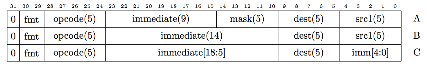
-
fmt - describes operand types.
Value
dest
src1
Masked
Encoding
00
Scalar
Scalar
N
B
01
Vector
Vector
N
B
10
Scalar
n/a
N
C
11
Vector
Vector
Y
A
-
mask, dest, src1 - Same as register arithmetic, described above
-
imm - Immediate operand. Processor sign extends this value and uses it as the second operand. If this instruction does not have a mask, it uses the alternative format with a larger immediate field.
-
opcode - Immediate instructions share the same opcodes as register arithmetic instructions, but only encode the low 5 bits.
The 'move' instruction can load a small constant into a register:
move s0, 17'movehi' is a special instruction that uses format 2 with the 'move' opcode. It copies the 19 bit immediate value to the most significant 19 bits of the destination register and sets the least significant 13 bits of the destination register to zero. It can be followed by an 'or' instruction to copy a 32-bit constant into a register.
The assembler expands the 'li' pseudo instruction to a movehi/or pair that copies a 32-bit constant into a register. For example the assembler expands this:
li s0, 0x12345678To this:
movehi s0, 0x91A2
or s0, s0, 0x1678
The lea pseudo instruction moves the absolute address of a label into a register:
lea s0, my_labelThe assembler converts this to a movehi/or combination like 'li', but also emits ELF relocations so the linker/loader adjusts the values depending on where the label ends up in memory.
The nop (no operation) instruction is encoded as 00000000. This disassembles to 'or s0, s0, 0'--which has no effect--but hardware detects this specific encoding and can optimize handling of it.
A memory instruction moves a value between a register and a memory location. It computes the memory address using a base register and a constant offset. Scalar memory operations can access 8, 16, or 32 bit values. The base address and offset are always multiples of bytes regardless of the access size, but these instructions raise an alignment fault if an access address is not aligned on its size. Memory accesses use little-endian byte order. A load instruction that is smaller than 32 bits and has the 's' suffix sign extends the result. An instructions with the 'u' suffix zero extends it.
This is the syntax:
load_32 s1, (s2)   # load the value from address s2 into s1
load_32 s1, 12(s2) # load the value from address s2 + 12 into s1
load_s8 s1, (s2)   # Load and sign extend byte from addr s2 into s1
load_u16 s1, (s2)  # Load and zero extend short from addr s2 into s1
store_32 s1, (s2)  # Store the 32-bit value from s1 into addr s2
store_8 s1, (s2)   # Store the byte from s1 into addr s2
Memory accesses in the physical address range 0xffff0000 to 0xffffffff perform memory mapped device IO. These must be 32-bit scalar load/stores, aligned on a 32-bit boundary as normal loads. If these are not, behavior is undefined.
There are two vector addressing modes. A block load uses a scalar base pointer and loads 16 contiguous 32-bit values. It adds an optional offset to the base pointer. If the computed address is not aligned on a multiple of the vector size (64 bytes), the instruction raises an alignment fault. For example:
load_v v1, 4(s6)Which is equivalent to this pseudocode (assuming bit 0 of the mask is the least significant bit)
for lane = 0 to 15
    if mask[lane] or instruction not masked
        dest[lane] = memory[pointerReg + lane - 4 + immediate offset]
A scatter/gather memory access uses each lane of a source vector as a pointer for the same lane in the src/dest register. It may add an immediate offset to each one. It only loads 32-bit values. If a computed lane address is not aligned on a 32-bit boundary, the instruction raises an alignment fault. It may also specify a mask:
load_gath v1, 12(v2)
load_gath v1, s1, 12(v2)
It is equivalent to:
for lane = 0 to 15
    if mask[lane] or instruction not masked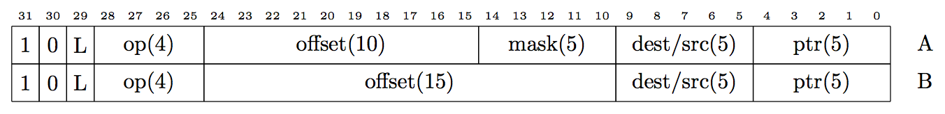
dest[lane] = memory[pointerReg[lane] + immediate offset]There are two formats of memory access instructions: one with a mask, one without. The op field encodes whether the mask field (which is only used for vector operations) is present. An instructions that has a mask field has the _masked suffix on its mnemonic.
-
L - If this is one, load from memory to a register, otherwise store from a register to memory. For control register accesses, a load indicates a transfer from a control register to a general purpose register, and vice versa.
-
dest/src – For loads, write the fetched value into this register. For stores, store this value from this register to memory. A synchronized store also updates this register to indicate success.
-
ptr – For control register accesses, this is the index of the control register. Other memory transfers use this register value to compute addresses based on the access type (described below).
-
mask - Controls which lanes to transfer. Lanes disabled via the mask do not generate memory access cycles.
-
offset – Offset in bytes to add to pointer (in a manner dependent on addressing mode). The processor sign extends this before addition, allowing negative and positive offsets.
-
op – Encodes the access type. Using an op not in this list raises an invalid instruction fault.
Value
Size
Enc
Mnemonic
Description
0000
8 bit
B
load_u8/store_8
Loads zero extend to 32-bit
0001
8 bit ext
B
load_s8
Loads sign extend to 32-bit
0010
16 bit
B
load_u16/store_16
Loads zero extend to 32-bit
0011
16 bit ext
B
load_s16
Loads sign extend to 32-bit
0100
32 bit
B
load_32/store_32
0101
32 bit
B
load_sync/store_sync
synchronized, described below
0110
32 bit
B
getcr/setcr
transfer to/from control register
0111
32 bit
B
load_v/store_v
Block vector transfer
1000
32 bit
A
load_v_mask/store_v_mask
Masked block vector transfer
1101
32 bit
B
load_gath/store_scat
Scatter/gather transfer
1110
32 bit
A
load_gath_mask/store_scat_mask
Masked scatter/gather transfer
Special load/store instructions enable multiprocessor synchronization (Some other architectures refer to these as load linked/store conditional). Programs can use these to implement atomic arithmetic and spinlocks. When the processor executes a synchronized load, the L2 cache records the address. The following synchronized store checks if any other threads have written to that cache line since the load. If one has, the instruction doesn't update the cache and writes 0 to the 'source' register. Otherwise, it updates the cache and writes 1 to the source register. The mnemonics have a _sync suffix:
load_sync s0, 12(s1)
store_sync s3, (s1)
In this example, the store_sync instruction updates s3 as a side effect, depending on success. Synchronized accesses are 32-bits wide.
Here is an example of code that performs sync_fetch_and_add. The address of the memory location is in s0. When this returns, the register s3 contains the return value (previous value before the increment):
loop:  load_sync s1, (s0)     # Load current value
       add_i s2, s1, 1        # Compute incremented value
       move s3, s1            # Save previous value
       store_sync s2, (s0)    # Try to write back increment value
bz s2, loop # If store_sync failed, retryThis system uses a relaxed memory consistency model. Although it guarantees read-to-read and write-to-write ordering between threads, it does not guarantee write-to-read ordering. This is sometimes referred to as Processor Consistency.
For example, given the following code:
volatile int a = 0;
volatile int b = 0;

void core1()
{
    a = 1;
    printf("b = %d", b);
}

int core2()
{
    b = 1;
    printf("a = %d", a);
}
At first glance, it might not seem possible for this to output “a = 0 b = 0,” because at least one assignment must occur before either of the prints. But this can happen because this design can reorder stores after loads.
Reordering only occurs between hardware threads. We guarantee that threads always see their own stores in order. For example, the following program would never print “a = 0.”
int a = 0;

void core1()
{
    a = 1;
    printf("a = %d", a);
}
When needed, software can force write-to-read ordering using the membar instruction, which the section on cache control below describes. The sync_synchronize intrinsic emits this from C. For example, the following code always prints at least one of the variables as 1:
volatile int a = 0;
volatile int b = 0;

void core1()
{
    a = 1;
    sync_synchronize();
    printf("b = %d", b);
}

int core2()
{
    b = 1;
    sync_synchronize();
    printf("a = %d", a);
}Although these instructions use the memory instruction encoding, they do not access memory. The getcr instruction transfers a value from a control registers to a general purpose register. The setcr instruction does the opposite.
setcr s10, 12
getcr s8, 30
In the table below, registers marked 'thread' have a separate instance per thread. Those marked 'shared' have a single instance per core that is visible to all thread (but not by threads on other cores).
Accessing any control register (read or write) when the processor is not in supervisor mode raises a privileged operation fault. Although it might seem useful to allow some of these registers to be accessible from user mode, doing so would violate Popek & Goldberg virtualization requirements because these are "behavior sensitive instructions."
Accessing an index not in this list has undefined behavior.
| Index | Read/Write | Shared/Per-Thread | Description |
|---|---|---|---|
| 0 | r | thread | Global Thread ID 1 |
| 1 | rw | shared | Exception Handler Address 2 |
| 2 | rw | thread | Trap PC 2 |
| 3 | r | thread | Trap Cause 2 |
| 4 | rw | thread | Processor flags 4 |
| 5 | r | thread | Access address of last memory trap 2 |
| 6 | r | shared | Count of processor cycles since reset |
| 7 | rw | shared | TLB miss handler address (physical address) 3 |
| 8 | rw | thread | Saved flags value 2 |
| 9 | rw | thread | Current address space ID 3 |
| 10 | rw | thread | Current page directory base 6 |
| 11 | rw | thread | Scratchpad register 0 5 |
| 12 | rw | thread | Scratchpad register 1 |
| 13 | rw | thread | Subcycle of instruction that a trap interrupted (for scatter/gather memory access) |
| 14 | rw | thread | Interrupt Enable 2 |
| 15 | w | thread | Interrupt Ack 2 |
| 16 | r | thread | Interrupt Pending 2 |
| 17 | rw | shared | Interrupt Trigger mode 2 |
| 18 | rw | shared | Bi-directional JTAG data transfer |
| 19 | r | thread | Index of last syscall instruction. |
| 20 | w | shared | Suspend thread 7 |
| 21 | w | shared | Resume thread 7 |
| 22 | w | shared | Performance counter 0 event select 8 |
| 23 | w | shared | Performance counter 1 event select |
| 24 | w | shared | Performance counter 0 low 32 bits |
| 25 | w | shared | Performance counter 0 high 32 bits |
| 26 | w | shared | Performance counter 1 low 32 bits |
| 27 | w | shared | Performance counter 1 high 32 bits |
-
Bits 31-2 are the core index, bits 1-0 are the thread ID (assuming four threads per core).
-
See Trap/Interrupt Handling section.
-
See Virtual Memory section.
-
Flags
Bit
Usage
0
Interrupt enable. The processor does not dispatch interrupts on the thread while this is 0.
1
MMU enable. When this is one, the TLB performs address translations for the current thread. If not, physical addresses are the same as virtual addresses.
2
Supervisor mode. This enables access to memory pages with the supervisor bit set and system instructions described elsewhere in this document (eret, setcr, etc.)
-
Available to stash general purpose register values temporarily during the interrupt service routine.
-
Since TLB misses are handled by software, this is just a convenient way to pass the page directory pointer to the TLB miss handler routine. However, if a hardware page walker were implemented, it would read from this register.
-
These registers are shared by all cores. Each bit corresponds to a thread, all cores are represented in order. When writing to the resume register, any bits that are 1 will wake the corresponding thread. Bits with zeroes are unaffected. The suspend register works similarly.
-
The following performance events are available
Index
Event
0
Interrupt
1
Store rollback
2
Store
3
Instruction retired
4
Instruction issued
5
L1 instruction cache miss
6
L1 instruction cache hit
7
Instruction TLB miss
8
L1 data cache miss
9
L1 data cache hit
10
Data TLB miss
11
Unconditional branch
12
Conditional branch, taken
13
Conditional branch, not taken
A branch instruction causes the program counter to jump to another address. A conditional branch uses the value in source scalar register to determine whether to take the branch.
b label
b s0
bnz s0, label
bz s0, label
call label
call s0
eret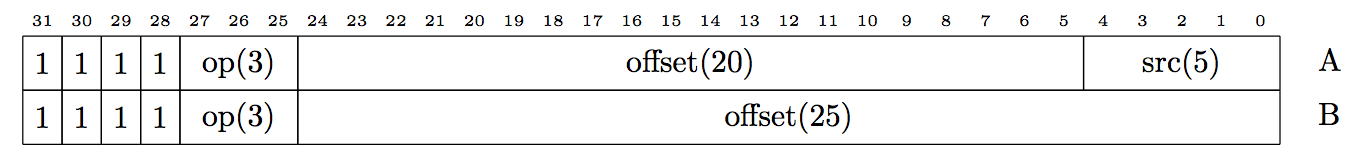
-
src – Source register, described below
-
offset - Signed offset to destination address, divided by four bytes, from the branching instruction (dest_pc - source_pc) / 4. For example, if an instruction at address 0x1000 branchs to address 0x1234, the offset field contains 0x8d. For a 20-bit offset, the maximum range is ±4MB. For a 25-bit offset, the maximum range is ±128MB.
-
op – Operation:
Value
Enc
Mnemonic
Description
000
A
b
Branch unconditionally to address in src
001
A
bz
If value in src is zero, branch to address indicated by offset.
010
A
bnz
If value in src is not zero, branch to address indicated by offset.
011
B
b
Branch unconditionally to branch to address indicated by offset.
100
B
call
Branch to branch to address indicated by offset and save pc + 4 into ra (return address) register, index 31
110
A
call
Branch to address in src and save pc + 4 into ra register
111
A
eret
Return from exception. Jump to address in control register 2 and copy previous control register state back to current (see Trap/Interrupt Handling section for more details). This raises a privileged operation fault if not executed in supervisor mode.
Executing a branch instruction with an operation that is not in this list raises an invalid instruction fault.
'ret' is a pseudo instruction that expands to a indirect branch to the return address register (b ra).
itlbinsert s0, s1    (where s0 is the virtual address and s1 is the TLB contents)
dtlbinsert s0, s1
tlbinval s0
tlbinvalall
dinvalidate s0
iinvalidate s0
dflush s0
membar
-
ptr – Base address, scalar register. For TLB insertion, this is the virtual address.
-
tlb entry - Index of register that contains 32 bit TLB contents (described in the Virtual Memory section) for dtlb/itlbinsert
-
op - cache operation. mode in the table below indicates when it is legal to use this instruction. S is supervisor only, U/S is user or supervisor mode. If the program attempts to use a supervisor only instruction in user mode, it raises a privileged operation fault.
Opcode
Instruction
Mode
Description
000
dltbinsert
S
Insert a new TLB entry from register tlb entry for virtual address ptr. If an entry for the virtual address is already in the TLB, update it. If necessary, evict other entries from the TLB to make room for this one. 2 3
001
dinvalidate
S
The register address represents a virtual address. The processor will perform a virtual to physical translation for the current address space and remove lines matching that physical address from L1 data caches of all cores and the L2 cache. If there is dirty data in the L2 cache, it will discard it without writing it back, losing updates. 1
010
dflush
U/S
Similar to dinvalidate, but instead of evicting lines, it will write them back to memory if they are resident and dirty. 1
011
iinvalidate
U/S
Remove cache lines that match the virtual address from the instruction cache. Does not invalidate the line in the data cache or the L2 cache. 1
100
membar
U/S
Memory barrier. As described in the section on load/store instruction, this processor uses a relaxed memory consistency model. The membar instruction allows forcing write-to-read ordering by waiting for the current thread to commit outstanding stores (or cache control commands) to the L2 cache. When this instruction completes, all L1 caches of all cores see the results of any stores executed previously by the current thread.
101
tlbinval
S
Invalidate instruction and data TLB entries for address. 2
110
tlbinvalall
S
Invalidate all entries in instruction and data TLBs for all ASIDs. 2
111
itlbinsert
S
Insert a new entry into the instruction TLB, same behavior as dtlbinsert. 2 3
- dflush, dinvalidate, and iinvalidate do not wait for the operation to complete, but a membar instruction issued after one of these instructions does.
- A TLB instruction only updates entries on the core it is issued on. An invalidate instruction only affects the entry for the current ASID, unless the page at the address is global, in which case it invalidates it for all ASIDs. It can take a few cycles for the new translation to take effect because of pipeline delay, but the updates are not queued and membar does not wait for the update to complete. The Virtual Memory section describes this in more detail.
- The ASID for the new TLB entry will be copied from the current ASID control register.
Other notes
- If a program dynamically generates code (for example, JIT compilation), it must execute the iinvalidate instruction to reload instruction cache lines, as the processor does not do this automatically as a side effect of memory stores.
- A program should execute dinvalidate to reload data that an external device or processor DMAed into system memory.
- If a processor must execute code DMAed or loaded into memory by an external device or host processor, it must execute dinvalidate (to reload the L2 cache) followed by iinvalidate (to reload the icache).
A trap may occur for several reasons:
- A instruction faults by performing an invalid action, like an unaligned memory access.
- An interrupt occurs when an external device requests access. These occur at an instruction boundary. The processor only dispatches an interrupt if the thread has enabled it in the processor flags control register.
- The processor executes a syscall or breakpoint instruction. These switch from user to supervisor mode and jump into kernel code.
Traps are precise in this architecture: the processor guarantees that all instructions before the instruction at which the trap occurred have completed, and all instruction after that instruction have not. This allows the thread to resume properly after the trap handler software routine returns.
When a trap occurs, the processor performs the following actions:
- Copy the contents of the processor flags control register into the saved flags control register
- Copy the contents of the current program counter into the trap program counter control register
- For a multi-cycle instruction like scatter/gather memory accesses, copy the current subcycle into the subcycle control register.
- Disable interrupts
- Set the value of the trap cause control register
- Set the mode to supervisor in the processor flags control register.
- Set the program counter to the address in the exception handler address control register
The processor handles a TLB miss exception a bit differently, described in the Virtual Memory section
The trap cause control register has the following format:

-
C Cache type. Only valid for memory access traps (IDs 5-10 below)
- 0 - Instruction Cache
- 1 - Data Cache
-
S Store. Only valid for memory access traps.
- 0 - load operation caused trap
- 1 - store operation caused trap
-
Type of trap:
ID
Description
0
No trap (reset)
1
Illegal instruction
2
Privileged operation in user mode (setcr, eret, itlbinsert, dtlbinsert)
3
External interrupt
4
syscall (system call) instruction executed
5
Unaligned memory access
6
Page fault (page not present)
7
TLB miss
8
Write to read only page
9
Attempt to access supervisor page from user process
10
Attempt to fetch instruction from a page without the execute bit set
11
breakpoint instruction executed
When the trap handler completes, it can use the eret instruction to return. This performs the following actions:
- Copy the contents of the saved flags control register back to the processor flags control register (which may switch out of supervisor mode and re-enable interrupts).
- If this is a multi-cycle instruction, restore the subcycle from the subcycle control register.
- Jump to the address in the trap PC control register.
Nyuzi supports two levels of nested traps, which allows handling a TLB miss while in the middle of another trap service routine. When a trap occurs, it saves the following trap specific control registers. The eret instruction restores them:
| Index | Description |
|---|---|
| 2 | Trap PC |
| 3 | Reason last trap occurred |
| 5 | Access address of last memory trap |
| 8 | Saved flags value |
| 11 | Scratchpad register 0 |
| 12 | Scratchpad register 1 |
| 13 | Subcycle of instruction that a trap interrupted |
There are four control registers (14-17) that configure external interrupt handling. In each register, there is one bit per external interrupt, with bit 0 corresponding to interrupt source 0.
- Interrupt Mask: Configure which external interrupt sources cause an interrupt for the each thread. A 1 bit enables.
- Interrupt Ack: This is only valid for edge triggered interrupts. For each set bit, this resets the latched interrupt for the corresponding source. An ISR must do this before returning for an edge triggered interrupt.
- Interrupt Pending: Indicates which interrupts are pending. The software routine can iterate through the bits and handle the interrupts in turn.
- Interrupt Trigger Mode: A 1 bit indicates the interrupt is level triggered and is be raised if the interrupt input is in the high state. A 0 bit indicates the interrupt is edge triggered and is latched when the signal transitions from low to high.
Each thread can independently enable virtual address translation for itself setting the MMU enable bit in the processor flags control register. When the processor boots, translation is disabled for all threads.
Cores have separate translation lookaside buffers (TLBs) for the L1 instruction and data caches. Each core's TLBs are shared by all threads on it, but independent of other cores. Each TLB entry includes:
- Physical page number
- A set of flag bits
- An address space ID
Flag bits include:
- G: Global If this is set, ignore the address space ID when performing TLB lookup. The page appears in all address spaces (see below).
- S: Supervisor Thread can only access page if it is in supervisor mode. If it accesses this page when not in supervisor mode, it raises a supervisor memory access fault.
- X: Executable If a thread attempts to execute an instruction from a page that does not have this bit set, it raises an execute fault.
- W: Writeable If this is not set on a data TLB entry and the thread attempts to write, it raises a write protect fault.
- P: Present If this is not set in the TLB entry, accessing the page raises a page fault.
TLBs are managed by software. If a thread has enabled the MMU and accesses an address that doesn't have a valid TLB entry, it raises a TLB miss trap. An interrupt service routine reads the page table and inserts an entry into the TLB using the itlbinsert and dtlbinsert instructions, which use the following format for TLB contents:

A TLB miss behaves like a normal trap, except:
- It disables MMU translation for the trapping thread.
- Instead of jumping to the normal trap handler (which is a virtual address), it jumps to the value contained in the TLB trap handler control register, which is a physical address.
The TLB miss handler runs with the MMU disabled to avoid a nested TLB miss occurring in the middle of it, which would cause an infinite loop. This also allows it to access page tables without needing to map them into virtual memory.
Each entry in the TLB has an address space identifier (ASID). Each thread also stores an ASID in a control register. The hardware uses these in two ways:
- When looking up an address in the TLB, if the global flag is not set on the TLB entry, the processor only matches it if its ASID matches the ASID control register.
- The itlbinsert and dtlbinsert instructions copy the ASID from the control register into the TLB entry.
The ASID has two purposes:
- Allow threads on the same core to run in different address spaces. Since all threads share the TLB, the same virtual address may have different physical mappings for each thread.
- As an optimization to allow context switches without having to flush the entire TLB.
When the processor writes a new TLB entry (using the itlbinsert or dtlbinsert instruction), the ASID will be copied from the current ASID control register.
The ASID is 8 bits, which allows up to 256 virtual address spaces. If there are more than that, an operating system may dynamically reassign them, but must execute a full TLB flush instruction (tlbinvalall) when switching address spaces to invalidate other mappings for that ASID.