Laser Cutting of Parts
This document will describe the workflow necessary to go from a part design in SolidWorks to a cut piece of physical material, using an online vendor. Two different options / workflows will be presented, both of which require a 2D file.
Think of a 2D file as capturing a specific view or face of a 3D part.
In general, all online vendors require a 2D geometry file be uploaded to their site, after which you can select the material, thickness, bend angles, etc. of the part you'd like to receive. Laser cutting is a typical process employed by online vendors.
In general, there are two approaches you can take:
- (Preferred) Use a pre-exported 2D file (provided by Input-Inc.), or
- Export a part to a 2D file yourself
The workflow option you choose may depend on several factors:
- a pre-exported 2D file is not available (but we're working in it!)
- your desire to learn more about the workflow required to export a 2D file
- if you have modified the part design to suit your own robot build, or the pre-exported file is otherwise insufficient for you.
Both workflow options will be described independently in sections below.
Prerequisites required:
- SolidWorks for Makers 2024
- Access to the Input-Inc. CAD repository (The February 2024 CAD Release will be referenced in the included examples)
Note: A first obvious contrast between the options / workflows presented below will be in the different file formats used for each: DWG (.dwg) files vs. DXF (.dxf) files. For the purposes of this document, and for the workflows described, these two file formats can be considered to be interchangeable. Both are indeed 2D CAD files. DWG files are in a binary format (and therefore smaller in file size) whereas DXF files are text-based (ASCII) files. Most online laser cutting vendors accept both file types.
However, many vendors will offer some optional post-processing services for additional fees. A few of the most beneficial post-processing services may include:
- Bending
- Hardware Insertion (such as PEM nuts)
- Tapping of holes
- Countersinking of holes (where flat-head fasteners will be used)
Bending may be the most popular post-processing service that robot builders use, as creating accurate bends at home can prove to be problematic. Similarly, installation of PEM nuts can be difficult to do properly for the home robot builder. As such, bending and hardware insertion are both covered in the examples provided in this document. Other services, such as tapping and countersinking of holes will NOT be covered, as it is typically not cost-effective to have those done.
This document will refence / utilize the online vendor SendCutSend for examples. Other sites exist (such as OSHCut ) that also provide quality parts, but we have found SendCutSend to be the most cost effective and helpful vendor.
(Note: a 3rd potential workflow option exists, which is not included in the scope of this document: using SendCutSend's SolidWorks plug-in. It is not included here since it is currently in Beta at the time this document was authored.)
The Input-Inc. Team works diligently to make pre-exported files available, with more files being added to the CAD repository all the time. As such, you may often find that a pre-exported file exists for a part you want cut, and this can greatly simplify your workflow.
This section will describe how to:
- locate the pre-existing files.
- determine the proper material to use
- determine the material thickness
- upload the 2D file on SendCutSend's site
- configure and order the part
A simple example part will be used as a full complete walkthrough of the above process.
In addition, several more examples will be used to illustrate more complex examples, including those that require:
- bends
- fastener installation
- minor post-processing due to SendCutSend limitations
Using pre-exported files is the preferred workflow (as opposed to making your own 2D CAD files). This not only saves you time, but also mitigates issues you may encounter with having parts laser cut by SendCutSend due to their process limitations. In other words, the pre-exported files have been checked against SendCutSend's process parameters... and in some cases have been modified slightly to ensure SendCutSend can make the parts. More details will be included in each of the examples below.
NOTE: Before continuing, proceed to SendCutSend and create an account if you haven't already.
In this example, we will use the pre-exported 2D file to make the Quick-Release Plates for the Upper Torso. Specifically, the part is named [TUPR-A-COMN-04] Quick-Release Plate and they are highlighted in blue in the screenshot of the [TUPR] Upper Torso (Main Structure) assembly shown below.
Note that there are 2 of the same part used in this assembly.

It's important to be able to interrogate the design and take note of the quantity of a part used in an assembly, because SendCutSend typically has significant discounts for any quantities > 1.
As stated previously, the parts we are looking to create are quantity 2 of [TUPR-A-COMN-04] Quick-Release Plate.
The first step will be to determine the recommended material and measure the part thickness. To do this, we need to open the 3D CAD part file for this part. That can be done in one of two ways:
- open the [TUPR] Upper Torso (Main Structure) .SLDASM assembly file and open the part from there, or
- navigate to the [TUPR-A-COMN-04] Quick-Release Plate .SLDPRT 3D part file directly.
Let's do the latter. The [TUPR-A-COMN-04] Quick-Release Plate 3D part file is located here:

Note how the folder structure matches the Part's file name, helping to find the part easily.
Open this [TUPR-A-COMN-04] Quick-Release Plate part file in SolidWorks.
In the FeatureManager Design Tree (left column), we can see that the recommended material is 6061-T6 Aluminum (see screenshot below). Make note if this and continue.
Note: the "(SS)" suffix on the material in the screenshot below does not indicate Stainless Steel! It is SolidWorks nomenclature to indicate that Stress-Strain curves are defined for this material. Don't let that confuse you!

Now, we need to determine the part thickness. Select the Evaluate tab and then click on the Measure tool. The mouse icon will change to a tape measure.
Now, click to select a single edge of the part to see the edge length as shown below:

We can see that this part is intended to be 0.1875" thick. Make note of this and continue.
NOTE: Only use drawings that are within the "[DRAW] Drawings" sub-folder of the parts you want. The Drawings folders are specific to the version of the assembly they are contained in.
Going back to the folder where we opened the part file from, we can see that there is a "[DRAW] Drawings" sub-folder:

If we go into that "[DRAW] Drawings" sub-folder, we see several files. The file indicated in the image below is the one we want. Note that it has the same file name as the 3D part we opened, but with a .DWG file extension:

Don't attempt to open this .DWG file... this is the file we will upload to SendCutSend
At this point, we are ready to upload the pre-exported drawing to SendCutSend. Go to the site and login.
Now, verify that 'Parts' is selected in the top menu bar, and then drag and drop the [TUPR-A-COMN-04] Quick-Release Plate.DWG file to the area indicated, as shown below:

Wait a few seconds for the part to be processed, and you will be presented with a preview of the part:

The units are indeed in inches, so click the CONFIRM button to continue.
Now, we will select the Material. We know from our previous work that the correct material for this part is 6061 Aluminum, so click through the following selections:


You will now be asked to select the Thickness, which we determined previously to be 0.1875". Make that selection:

Once the material thickness has been selected as instructed above, you will then be prompted to select the quantity. Set the Quantity to 2 as previously determined and shown below, then click the NEXT button.

You will now be prompted to select Additional Services as shown below.

This part does not require any additional Services, so click NEXT again.
Now, you will be presented with choices to make for Finishing. Deburring (a free service) is always automatically selected as a Finishing operation, if it's available (depending on part size) as shown below:

Leave that selected and click the ADD TO CART button.

Select to View the Cart, and verify that your Material, Thickness, and Services selections are correct:

Congratulations! You've configured your first part for laser cutting!
Other examples below will decribe additional complications to this process for more complex parts.
In this example, we will use the pre-exported 2D file to make the Side Plates for the Middle Torso. Specifically, the parts are named [TMID-A-COMN-00L] Side Plate (Left) and [TMID-A-COMN-00-R] Side Plate (Right) and are highlighted in blue in the screenshot of the [TMID] Middle Torso assembly shown below.

The difference illustrated in this example, compared to Example 1, is that this part has countersinks. For example, this is a view of the Left part with the countersinks highlighted:

What does that mean to us, in regard to ordering parts from SendCutSend? Investigating the part geometry, we can see that the Left and Right Side Plates are identical, except for the countersinks.
Stated a different way, the countersinks are what turn a side plate into either a Left or Right side plate for this example. The remaining geometry is identical.
In addition, Countersinks are a Service option provided by SendCutSend that it is typically NOT cost effective to use. That means we prefer to add the countersinks ourselves after the parts arrive.
That means if we can eliminate the countersinks from the geometry, we can order two of the same part and take advantage of SendCutSend's quantity discounts!
And, the Input Inc. team has already eliminated the countersinks from the Pre-exported 2D file, so this example quickly becomes exactly like Example 1! (This is another advantge of using the Pre-exported 2D files)
Let's continue with a few of the steps in SolidWorks as a refresher of Example 1 just in case...
As stated previously, the parts we are looking to create are [TMID-A-COMN-00L] Side Plate (Left) and [TMID-A-COMN-00-R] Side Plate (Right).
The 3D parts files (with .SLDPRT file extensions) are located as shown in the screenshot below, and again the part naming convention helps us locate the appropriate sub-folder:

Open one of the Parts in SolidWorks, and in the FeatureManager Design Tree (left column), we can see that the recommended material is 316 Stainless Steel. Make note if this and continue.

Now, we need to determine the part thickness. Select the Evaluate tab and then click on the Measure tool. Now, click to select a single edge of the part to see the edge length as shown below:

We can see that this part is intended to be 0.125" thick. Make note of this and continue.
NOTE: Only use drawings that are within the "[DRAW] Drawings" sub-folder of the parts you want. The Drawings folders are specific to the version of the assembly.
Going back to the folder where we opened the part file from, we can see that there is a "[DRAW] Drawings" sub-folder:

If we go into that "[DRAW] Drawings" sub-folder, we see several files. The file indicated in the image below is the one we want. Note that it has the same file name as the 3D part we opened, but with a .DWG file extension:

Don't attempt to open this .DWG file... this is the file we will upload to SendCutSend
Note that the pre-exported file has "(Left)" in the filename. Don't be concerned with this... it simply indicates the original filename of the part that was exported. The countersinks were removed by the Input Inc. team during that export process. See Example 2, Step 3 below for confirmation.
Now that we are aware that:
- We need 2 of the same part, since we will make them into a Left and Right by adding appropriate countersinks ourselves, and
- We have determined the Material, and
- We have determined the Thickness, and
- We know the .DWG file we need to upload,
...the rest of the process continues as before. Go back to Example 1, Step 3 as a refresher if necessary and continue from there the same as before.
We can immediately see that the Input Inc. team has properly eliminated the countersinks from the part, after uploading it to SendCutSend:

Now that we have worked through two simple examples, we will start to focus on some variations on those examples for more complicated parts. In the subsequent sections, we will not go through the entire process step-by-step, but instead highlight what is different from the simpler flat metal plate parts.
In this example, we will use [CRDL-V3-A-05] Actuator Strength Plate and highlighted in blue in the screenshot of the [CRDL-V3] Cradle Base.SLDASM assembly shown below:

This example will reference a part that requires multiple bends.
Bending is typically an operation that makes sense for SendCutSend to perform for us. Their process is very accurate and very cost-effective, helping us avoid the need to purchase costly equipment (or make costly mistakes!) at home.
This is a perfect example of why using pre-exported 2D files and drawings is preferred. The bending process requires knowledge of:
- The locations of the bends, and
- The angles of each bend
which would require manual interrogation of the part.
The pre-exported files and drawings provide these details, saving you time and mistakes.
For pre-exported parts that require bends, that Input Inc. team is actively working to create 2D Drawing Files, which will include a Bend Table, in addition to the pre-exported 2D (DWG) file.
The 2D Drawing Files are of a .SLDDRW file type, and can be opened in SolidWorks.
For this example, using [CRDL-V3-A-05] Actuator Strength Plate, we can find the 2D part (.DWG) file and the 2D Drawing File (.SLDDRW) here:

Let's assume that we've already opened the 3D part (.SLDPRT) file in SolidWorks to determine the proper material and thickness, as shown in previous examples.
Remember that the .DWG file is the file we upload to SendCutSend, but first let's open the .SLDDRW 2D Drawing File in SolidWorks.
Upon opening the file, we see a typical 2D Drawing layout as shown below:

We can see a Bend Table in the upper right corner, calling out bends A, B, and C.
The part view on the left has the 3 bend lines indicated as A, B, and C as well. You'll need to keep this drawing handy while configuring the part on SendCutSend's site.
Let's assume that you've already uploaded the 2D part (.DWG) file to SendCutSend's site, and have selected the proper material and thickness.
At that point, SendCutSend's site will ask you to Add Services. We've previously skipped past this part, but you can see now that Bending is an option for this part based on how it was exported:

Click on that Bending service, and the options will expand as shown:

Under the view of the part, select 2D, as it makes it easier to see the bend lines:
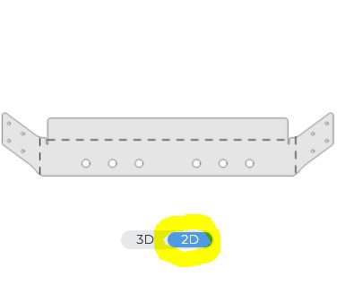
Now, notice that as you click to insert your cursor into one of the numerical angle fields that the associated bend line highlights on the 2D view of the part:

Use that feature, coupled with the Bend Table on the associated 2D Drawing to configure all 3 bends as shown below.

Note that for each bend, you must select both:
- the angle, and
- the direction (Up or Down)
For this part, where all 3 bends are the same angle, Up vs. Down direction doesn't really matter... as long as they are all the same. However, for more complicated parts where the bends are in opposite directions or not all 90 degrees this becomes important.
If you switch the view back to 3D, you can verify that your bends are configured properly, as they match the 3D part in SolidWorks:


The Bends are all now properly configured!
This example will be presented as more of a discussion, as opposed to previous "full walkthrough" examples.
Sometimes, features are required on the 3D parts that contradict SendCutSend's part design criteria or guidelines. One such case of this is when holes are too close to a bend line, as they may become distorted.
Due to SendCutSend's air gap bending process, each bend will have witness marks (or Die Lines) visible on the part, like this:

Any features within those 2 Die Lines would typically cause SendCutSend to raise a red flag, causing them to not make the part or asking you to redesign the part and resubmit it. This is because the bending operation can distort features inside of the Die Lines.
So, in cases like this, the Input Inc team is working diligently to create pre-exported 2D (.DWG) files that have remedied the issue.
To illustrate this, let's take a look at [TUPR-A-COMN-01] Front Plate used in the [TUPR] Upper Torso (Main Structure).SLDASM assembly.

Examine this part for a moment, and you'll see that it has a total of 18 #8 clearance holes:
- 4 on the bottom face, and
- 7 on the left flange, and
- 7 on the right flange
It turns out that the 7 holes on each of the side flanges are inside of the Die Lines. An illustration of this is below, which indicates the Die Line specification for the recommended material & thickness of this part:

You can see that the central holes (where one is shown on the right) just clears the die line, while the outer flange holes (on the left) cross the die line.
If you were to export this part to a 2D part file yourself, you'd need to modify the part to avoid this conflict with SendCutSend's bend criteria.
Luckily, the Input Inc. team has done this work for you: the pre-exported 2D part (.DWG) file has modified the 14 outside flange holes to be smaller in diameter, allowing SendCutSend to make the part without issue (or distorting the holes).
The as-received part will look like this, with one of the smaller holes indicated in red:

You will have to do minor post-processing after receiving the part, to drill out those 14 flange holes to a #8 clearance hole... using the provided holes as a centering feature. That's it!
This section therefore serves as notice that you need to compare the received parts against the 3D CAD to make sure you handle any minor post-processing required, as you would for creating countersinks, tapping holes, etc.
A more "severe" example than Example 4 above of the parts received from SendCutSend not matching the 3D CAD, as required to allow the parts to be manufactured, can be seen in the part [CSTR-COMN-01] Triangular Support used in the [CSTR] Main Structure.SLDASM assembly.
The 3D part file looks like this:

Of course you are always free to make this part yourself, but as-is it cannot be bent by SendCutSend as one piece.
The solution? The Input Inc. team has chosen to create the 2D part (.DWG) file as effectively one half of this part, such that you would need 2 pieces (one Left and one Right).
Uploading the associated 2D .DWG file to SendCutSend will show a part that looks like this before bending:

Simply configure and add this part to your cart twice, once with both bends UP, and once with both bends DOWN, and you will receive two parts that function as the original intent once assembled, as shown:

Upon receipt, add your countersinks like you normally would, and you've saved yourself a lot of hassle making this complicated part!
Another limitation to SendCutSend's Bending process is that there must be an external edge of the part parallel to the bend line. This means that, in some rare instances, "tabs" may be needed to be added external of the part to create this parallel edge. Upon receiving the part from SendCutSend, simply cut away these tabs like you would for other simple post-processing. In the rare instance that extra tabs are required, the Input Inc. team strives to include them in the pre-exported .DWG file as shown in the screenshot example below. The red line indicates cuts that would be made to remove the external tab.

We've spent a lot of time talking about Bending in previous examples, because it is such a valuable process for SendCutSend to provide for home robot builders.
A second valuable process that SendCutSend provides is Hardware Insertion. This example will describe the steps required to have PEM-type fasteners installed as an Additional Service. PEM-type fasteners are typically nuts that are pressed into a part, becoming a permanent feature of the part. This greatly simplifies the assembly process for us.
Note, is in previous Bending examples, this example will not be a full walkthrough but will instead focus on only the steps required to have fasteners of the right size properly installed for you by SendCutSend.
Let's us [CRDL-V3-A-00] Top Plate used in the [CRDL-V3] Cradle Base.SLDASM assembly.
The part, including the PEM-type fasteners, looks like the screenshot below (bottom view shown):

You can see the 20 PEM-type (pressed in) nuts on the insides of both left and right flanges.
The PEM nuts are 6-32 thread, Zinc plated, as indicated in the CAD:

Add the associated 2D Part (.DWG) to SendCutSend, set the material & thickness, configure the bends properly using the associated 2D Drawing (.SLDDRW) file, and the part will quickly take shape on SendCutSend.
While still on the Add Services portion of part configuration, click on the Hardware Insertion service as indicated below:

Now, look back at SolidWorks to interrogate the hole size where the PEM nuts will be installed, and we see that they are set to 0.189" diameter as shown below:

Back on SendCutSend's site, note that a list of holes where hardware can be inserted is provided automatically. Click on the OPEN CATALOG button for the 0.189" entry on the list as shown below:

You will then be asked to select a Hardware Category. Select NUT as indicated below:

From the list of nuts given, select the 6-32 Nut that is Zinc Plated. You can click the "i" bubble as highlighted below to verify which of the two 6-32 selections is Zinc plated.

.

Click Apply on your selection, and you will see the PEM nuts appear on the bent part. Note that the selected PEM nut will be installed automatically on every 0.189" hole... you do not need to select and configure each hole individually.
IMPORTANT! You must verify the side of the sheet metal that the PEM nut will reside! If necessary, use the Pull Direction selection (highlighted in red in the screenshot below) to reverse sides.

Verify one last time that the bend angles, bend direction, fastener type, and fastener side ("pull direction") are correct, and you are done!
Sometimes, you may find a need to export a 2D part file yourself, instead of using a pre-exported file. Perhaps you are building from an older CAD release that does not have a pre-exported 2D part file, or you've made some modifications to the CAD yourself such that a pre-exported 2D part file is no longer valid.
This section will work through an example, showing you how to create your own 2D Part file, including Bends, for upload to SendCutSend.
NOTE: this section will use .DXF as the 2D Part file format, as opposed to .DWG like we used for the pre-exported files. This is user preference; .DWG files are binary and take up less space, while .DXF is ASCII (readable) text and for sure compatible with SendCutSend.
This section will not include any upload or configuration of the example part on SendCutSend's site; once the .DXF file has been created, the rest of the process follows the examples discussed above (for pre-exported 2D Part files) exactly.
A map file is really only required when exporting parts that have bend lines or features that need to be uniquely indicated (by line type, etc.) to satisfy the requirements of the vendor you intend to use. However, installing the map file now, and making it a part of your standard workflow, will cause no harm and will help to standardize the process.
SendCutSend provides their own map file.
Download SendCutSend's map file by clicking this link: SendCutSend Map File
If your web browser is configured to prompt you where to save downloaded files, the file "save as" dialog window will appear as normal. Save the file named "sendcutsend_solidworks_map" to your preferred location, where you keep your build-related files.
However, if your web browser is configured such that it automatically saves downloaded files to a default location (without prompting you), your web browser will appear as if you've landed on an empty page and that nothing has happened. This is normal. Look to where your web browser automatically saves downloaded files, and you will see a 1KB-sized file named "sendcutsend_solidworks_map" with no file extension. Manually move this Map File to an appropriate place on your PC, and remember the path.
In SolidWorks, open any 3D Part (.SLDPRT) file. (There seems to be a bug that doesn't show Export options appropriately unless a part file is open first.)
Then, open the Options menu:

Note that you will likely need to scroll to the very bottom of the Tools menu to see the Options entry since there is a part file open.
In the Options dialog that opens, first select Export in the left column, then select DXF/DWG for the File Format as shown:

In the area shown below, click the Enable tickbox, and then use the ellipsis icon to browse for and select the Map File you saved earlier:

The map file is now installed, and will be automatically used every time you export to .DXF.
Open the part we will use for this workflow, which is [TMID-F-V2-COMN-01-R] Side Plate (Right).SLDPRT used in the [TMID-F] Upper Torso Hinge.SLDASM assembly.
The part looks like this:

Note that this part has countersinks and a bend. It is also created as a Sheet Metal part in SolidWorks, which means that we will create an un-bent flat pattern.
Since we are not using a pre-exported part, there is no 2D Drawing (.SLDDRW) with a Bend Table to view. We must measure the bend angles ourselves.
Use the measure tool to select two faces on opposite sides of the bend as shown below.

In this example, we have only 1 bend that is 90 degrees. Make note of this for bend configuration on SendCutSend's site later.
Typically, when exporting a part, you need to select a part face or viewport view as the 2D view of the part to export. However, since our example is drawn as a Sheet Metal part, SolidWorks will automatically flatten the part for us.
Select Export As... from the File menu:

Select an appropriate location to save the exported file, and make sure to set "Save as type:" to DXF as shown below:

You will now see the DXF / DWG Output options on the left in SolidWorks. Select the options as indicated below:

NOTE: if the part you are exporting is NOT a Sheet Metal part (such that the Sheet Metal option is not listed as an option), select "Faces/ loops / edges" instead and then select a face of the 3D part for 2D export, or select "Annotation views" to select a viewport view to export.
Once you've made the appropriate DXF/DWG Output selections, click the green checkmark ✔️ icon to continue.
SolidWorks will automatically bring up the Mapping dialog due to having a Map File configured. The settings should appear as below:

Click Ok to continue.
You will now see a 2D view of the flattened part shown in the DXF/DWG Cleanup dialog. Do not click save yet! We need to remove the countersink features...
The 2D view of the part we are exporting should look like this at this point:
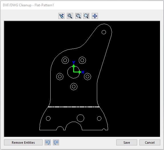
Note the 5 countersink features (indicated by concentric circles) around the large center hole. We need to delete those, as otherwise SendCutSend will make the part incorrectly.
To do so,
- click on one of the outer circles, then
- hold the Ctrl key while you click on the subsequent outer circles, until all 5 outer circles are highlighted red as shown below.
 Then, click the Remove Entities button.
The view should now look like this:

Click the Save button.
That's it! you now have a 2D Part (.DXF) file that you can upload to SendCutSend, and configure the material, thickness, and bends like in the previous examples.