7 Highway Network Management
In TRMG2, highway projects are managed using a master link layer and a list of project IDs to include in each scenario. When a scenario is being created, the scenario creation tool reads the user-provided list of project IDs, and includes those projects in the scenario network.
This arrangement facilitates model application in several ways:
- Central database of projects
- Avoids repetitive coding tasks
- Provides clarity as to which projects are included in a given scenario
This page provides guidance on how to use the project management system, which has been designed to be lightweight and easy to learn.
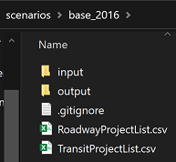
This layer is in the "master/networks" folder.
The layer contains fields for base and project attributes. All future year projects should be coded within this layer, using the coding guidance provided below. There is space for links to have up to 5 associated projects. Note that the master route system is built off of the master link layer.
Each scenario must have a copy of this file as an input. It is located in the top level of the scenario directory.
The file contains a single column named "ProjID" along with a list of project IDs that will be included in the scenario. Note that the order projects appear is important. Projects should be listed in the order that they will be implemented. The attributes associated with the link’s last project will be used to update values. See Project Coding for further details.

This file must be present even if no projects are being included in the scenario (a base year network). To create a base year network, simply create a RoadwayProjectList.csv file with the ProjID column without including any IDs.
Within the master link layer, use 'highway projects' to represent roadway widenings, new alignments or closings. Each project is associated with a user-defined project ID. During scenario creation, if the project ID is listed in the RoadwayProjectList.csv file, the project attributes overwrite the base attributes.
In general, create the .net file before starting any highway coding. Also, keep the MasterRoutes.rts file open (but it can be hidden) during highway coding. This method allows the transit route system to update automatically for most highway attribute changes.
- Dir - Standard TransCAD directional field. For a project, if a two-way link should be changed to one-way, change p1Dir (orp2Dir-p5Dir). Also make sure that the project AB/BA lanes correctly match the topology and link direction. If not, the scenario will build correctly, but the model run will result in an error.
- NCDOTClass - This field does not affect model output and is only used for reporting purposes. The NCDOT roadway classification is political and does not always accurately reflect the road's operating characteristics. For a project, this attribute can be maintained, ignored, or assign it to the most close fit.
- HCMType - Highway Capacity Manual Type which describes the operational characteristics of the link and is used to determine capacity and free flow speed (in conjunction with HCMMedian and Area Type). Acceptable values include Freeway, MLHighway, TLHighway, Superstreet, MajorArterial, Arterial, MajorCollector, Collector, Local, and CC (centroid connector).
- AB/BALanes - The number of lanes in the topological direction.
- PostedSpeed - Speed as posted on roadway signage. For transit only links (fixed guideway), average operating speed can be used.
- HCMMedian - This can be Restrictive (with median or barrier and divided facility), NonRestrictive (center turn lanes, one-way streets) or None (no median, typically two- or four-lane highways with no turn lane, median or barrier). This field is ignored for freeways and superstreets (restrictive median is assumed). In general, NonRestrictive gives a 4% capacity increase and Restrictive gives an 8% capacity increase. This attribute (in conjunction with HCMType and Area Type) are used to determine capacity.
- DTWB - Drive/Transit/Walk/Bike. Use this field to determine which modes are allowed on the link. Note that if a "D" is not included, vehicle trips will not be allowed to use the link. For a project, if the link does not contain “D” within this field, the link will not show up in the scenario roadway network.
- HOV - This can be None (No occupancy restriction) or HOV (Requires at least 2 occupants to use).
- BOSSS - Bus on Side Shoulder Speed is only used if busses are allowed to operate on the shoulder. The coded value is the maximum bus speed. In congested conditions, busses are only allowed to travel 15 mph faster than auto traffic.
- TollType This can be Free (no tolls), HOT (tolls but HOV is free) or Toll (everyone pays a toll). Value of toll is in two separate fields based on whether the vehicle has a toll transponder or not.
The calculation of capacity is based on a lookup table that uses values for HCMType, HCMMedian, and Areatype. Areatype is a model calculated value based on underlying land use. HCMType and HCMMedian are user input values as discussed above.
If you want to visualize how HCMType, HCMMedian, and Areatype impact capacity, see the attached spreadsheet: capacity_pivot.xlsx
If you want to better understand how the capacity values are derived, see the attached memo: Capacity Memo.pdf
There are several important pieces of information; read through carefully to understand thoroughly:
- There are multiple sets of project fields (e.g. p1ID, p2ID, p3ID). These accommodate links with multiple projects.
- All links associated with a given project should use the same project ID and should be coded in the same set of fields. For example, if project A1000 uses p2ID on a given link, then A1000 should use p2ID on all other project links.
- TRMG2 will check for errors where a project spans multiple fields (e.g. p1 and p2 fields) and try to reconcile mismatches. In some cases, the tool will not be able to reconcile projects into the same group and will create an error. In this case, the user should manually place projects in the same group. Either way, once attribute data is fixed, the Create Scenario step needs to be rerun.
- If a subset of links has two projects, A121 and A122, project A121 should use p1 attributes fields, and project A122 should use p2 attribute fields. If both A121 and A122 are included in a given scenario, the one listed last in RoadwayProjectList.csv will be used. This project will appear in the 'UpdatedWithP' field.
- The project ID fields (p1ID, p2ID,) are text fields. In the master_links layer, the project ID field can be a decimal number, however, when the project IDs appear in the RoadwayProjectList.csv file, they are treated as numbers. If they include a decimal and a zero at the end (e.g., 182.10), the zero will be dropped (e.g., 182.1). Therefore, if using numeric project IDs with decimals and zeros, ensure they do not end in a zero. If the project ID begins with a letter (e.g. A421.10), the project ID will be treated as a text field in the .csv file and will retain the zero. For best result, always begin a project iD with a letter.
To represent road closures, enter -99 into the project lane fields (e.g., p1ABLanes/p1BALanes). If the project is included in the scenario, the -99 lane information will cause the link to be removed. During scenario creation, after selecting the appropriate project attributes, the model takes a second pass and removes any link that has -99 in both lane fields.
New location projects have a -99 in the base lane fields (ABLanes/BALanes). If the project is not included in the scenario project list, these links get removed. If the project is included within the scenario project list, it remains in the network and gets the attributes associated with that project.
Turn penalties are often used to penalize or prohibit vehicle flows in the model that cannot (or are not) made in the real world. For example, as freeway congestion increases, the model might send vehicles down off-ramps and back up on-ramps to make use of excess capacity. However, turn penalties are based on link IDs which can change over time as the master link layer is edited.
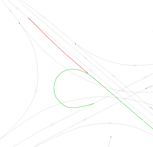
The preferred approach is to use link geography to prevent flows. This way, flow restrictions are clear. An example is shown below. The US-1 / I-40 interchange near Crossroads has auxiliary lanes that vehicles use to exit and enter the freeway. In the real world, it is physically possible for cars to use those lanes for through travel, but no meaningful volume does so. The image below shows how the link layer is modified to reflect this without using turn penalties. Vehicles can follow the red or green paths, but they cannot travel directly through the interchange on the auxiliary lane as the red and green paths do not intersect at a node.

A second example is shown below at the interchange of US 70 and NC 540 in Brier Creek. Again, an auxiliary lane exists and technically could be used for through trips. In the model, there is a small disconnect between the red and green links. This preserves the look of the link layer but prevents flow. (If the appearance is not important, the red link could be removed entirely.)
A third case is at the intersection of Walnut Street and Piney Plains.

In nearly every case, turn penalties are avoided by editing the link layer.
For all toll facilities, enter the toll cost in the base fields TollCostT/TollCostNT and identify the toll type in the project (p1-p5) TollType field. Note that the TollCost represents the total toll for that link. It can be entered as a lump sum for a particular section of toll road (e.g., at a toll gantry) or as a cost on all links of a project by multiplying the toll cost per mile by the link length.
A link should not be identified with TollCostT/TollCostNT unless it has TollCost assigned to it. For now, since the TollCost is a base attribute, the toll cost value cannot be adjusted during scenario creation. If toll gantries are being used, care must be taken to make sure that all links on the toll road are covered by a gantry to prevent assignment by non-tolled vehicles.
For TollCost: TollType = 'none' (toll is not applied) TollType = 'Toll' (toll is applied to all vehicles as: SOV – 1x, HOV – 1x, SUT – 2x, MUT – 4x) TollType = 'HOT' (all vehicles pay toll except HOV: SOV – 1x, HOV – 0x, SUT – 2x; MUT – 4x)
Note that the percentage of vehicles with transponders (TollCostT vs TollCostNT) can be changed in the model setup. See parameter 'TransponderRatio'.
For existing toll links (Triangle Expressway and NC 540 from I-40 to NC 55), tolls are applied at the specific links where existing toll gantries are located.
Because future toll gantry locations are unknown, for future toll links (NC540 from NC 55 east), tolls are applied on individual links on a per mile basis using the same rate (transponder $0.20/mile, non-transponder $0.39/mile).
For Managed Lane projects, the same toll values were used. Note that because of the model structure (congestion and delay are calculated differently and this impacts how traffic is assigned to parallel facilities), the managed lanes had very low assignments. Toll rates may be revisited in the future.
TRMG2 treats ramps differently than other roadway types. Capacities for ramps are not required. During a model run, the ramp HCMType takes the classification of a link that it is attached to. This change is noted in the scenario_links.dbd layer in the field ‘ramp’. This field is added to note that it was originally classified as a ramp but the HCMType was changed during the model run.
In a scenario_links.dbd file, notice that there are no HCMType = ‘ramp’ and Ramp = ‘yes’ for any link that was originally classified as a ramp. Note also that this may result in unexpected classification, especially where ramps are split between the on-ramp end and the off-ramp end. For example, in these cases it might classify the on-ramp end as “Freeway” and the off-ramp end as “Arterial.”
For controlled access facilities with ramps, a continuous on/off ramp (auxiliary lane) may require special coding. Some examples include:
- I-40 WB from Wade Ave to Harrison Ave (a continuous on/off ramp between the two interchanges that is just over 1 mile)
- I-40 EB from Wade Ave to NC 54 (a continuous on/off ramp between Wade and NC 54)
There is an informal agreement with FHWA (in regards to the MTP and air quality) that any auxiliary lane greater than 1 mile (measured from gore to gore) should be coded as an extra lane of capacity. Thus any auxiliary lane that is less than 1 mile should not be coded as an extra lane of capacity.
While reviewing the master links layer, if links have incorrectly coded base year attributes, those attributes should be updated (use the GitHub Issues to report errors).
If roadways have been improved after the current validation year (e.g. after 1/1/2020 for TRMG2v1.3), then the improvement should be reflected within a project field (p1ID-p4ID) and this project should be added to the first year of the MTP cycle project list (e.g. for the 2050 MTP, add within 2030 project list). When the validation year gets pushed out, these projects should be added to the base attributes of the new master links layer.