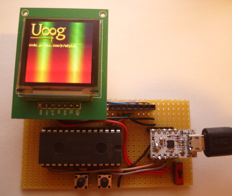
lpc1114
- U8glib on Cortex-M0 controller (LPC1114)
- SSD1351 OLED
- ISP (RS232) flash programming
The Proto-Board includes
- LPC1114FN28 (DIP28) Cortex-M0 controller
- UMFT234XF 3.3V USB to RS232 (TTL) converter
- 1x 100nF
- 2x Buttons (Reset and ISP Button)

The LPC controller enters programming mode by holding down the ISP (right) button then pressing and releasing the reset (left) button.
By default most of the GPIOs are pulled up by an internal resistor. No further pull up resistors are required for the buttons.
Programming of the device is done via RS232 (UART) interface. This can also be done with any other USB to serial converter.
- From https://launchpad.net/gcc-arm-embedded/ download and extract "Linux installation tarball"
- From http://sourceforge.net/projects/lpc21isp/files/ download, extract and compile (make) "lpc21isp tar file".
- Download and extract U8glib for ARM.
- Inside the folder of one of the U8glib examples: "make upload" will compile, link and upload the example. You might need to update the path to the tools in the Makefile. Remember to put the controller into programming mode (see above).
See INSTALL (http://code.google.com/p/u8glib/source/browse/tools/release/arm/INSTALL).