This project is a simplified version of floppy_disk_shield_2d. The FD-capture-lite has the following features:
- 2D/2DD floppy image capturing feature
- Create a floppy disk image in 'MFM' image file
- What you only need is an Arduino Uno R3 and a floppy disk drive. You don't need to have a special Arduino shield or any other hardware.
- The host program is written in Python. The host program communicates with Arduino via the onboard USB-serial interface on Arduino.
- ONLY genuine Arduino Uno R3 may work.
- This project uses AVR inline assembly code. The program has deep dependency on ATMega328 CPU.
- The Arduino Uno R3 clone boards may work (as long as the CPU is ATMega328) but the board should support 2Mbps serial I/F speed.
You just need to use some jump-wires to connect FDD to Arduino directry.
The host program requires 'pyserial' module.
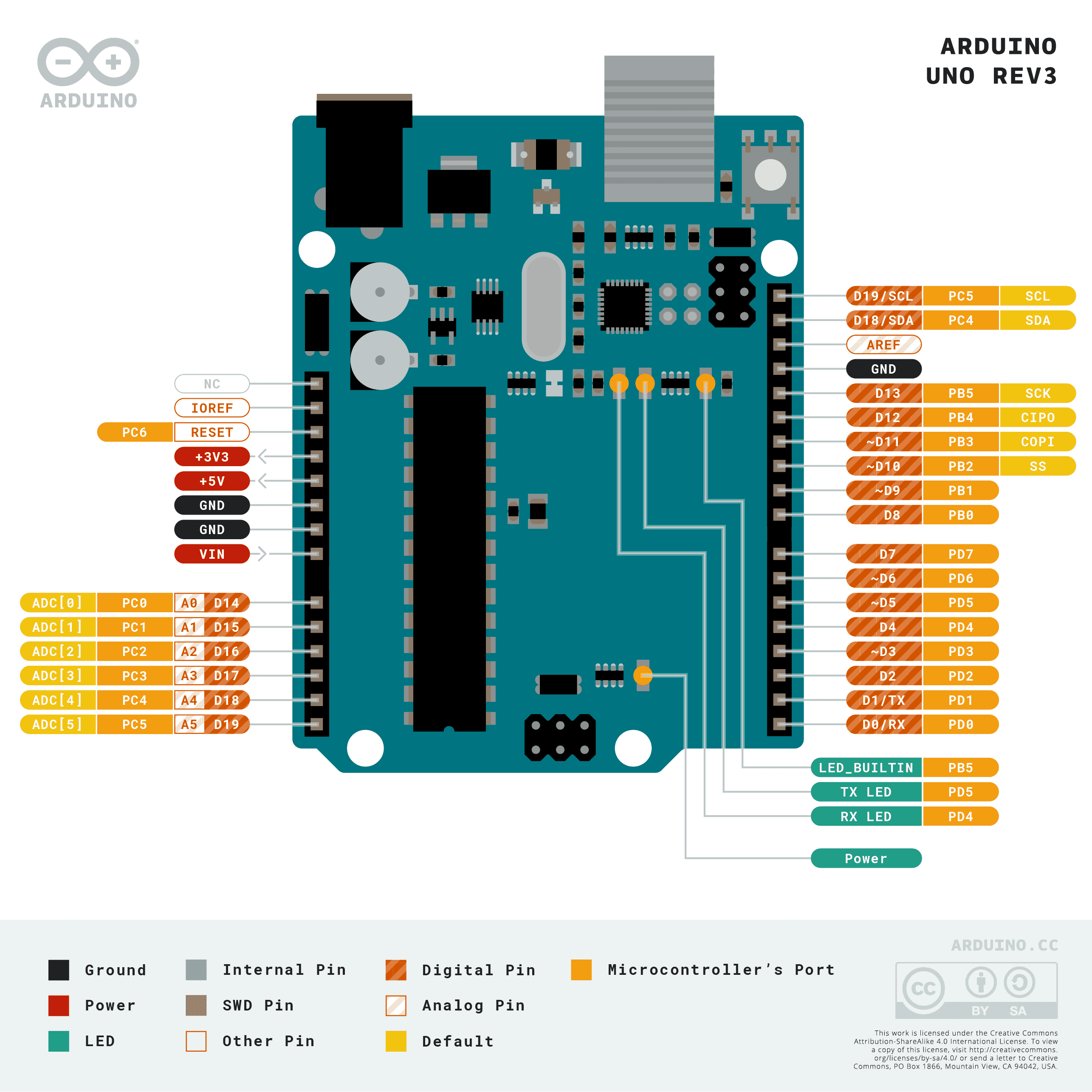
pip install -r requisites.txt| Signal | Arduino shield pins | FDD 34pin conn | Note |
|---|---|---|---|
| STEP | D2 | 20 | |
| HEAD LOAD | D3 | 4 | You can connect this signal to GND. The Arduino firmware drives this signal to LOW all the time. |
| MOTOR ON | D4 | 16 | You can connect this signal to GND. The Arduino firmware drives this signal to LOW all the time. |
| SIDE1 | D5 | 32 | |
| INDEX | D6 | 8 | |
| TRK00 | D7 | 26 | |
| RD | D8 | 30 | |
| DIR | D9 | 18 | |
| DS0 DS1 DS2 DS3 |
GND | 10 12 14 6 |
Depends on the setting of your FDD drive. You can connect all of them to GND if you have no idea which one to connect. The generic FDDs for IBM PCs use DS2 for drive select, and old 8-bit PCs may use DS0 or DS1 depending on which side the drive was installed. |
| GND | GND | 1,5,7,9,11,... | One of a odd pins except pin3 |
| Option | Description | |
|---|---|---|
-m |
--media |
Floppy media type. "2D"/"2DD"/"2HD" |
-p |
--port |
Arduino COM port. Example '-p COM7' |
This system uses the input-capture function on 16-bit timer 1 on the Arduino (ATMega328 CPU) to measure the data-pulse to data-pulse time. The timer 1 counts up at 16MHz (ClkIO 1:1).
- Pulse timing measurement (preparation): Collect some pulse-to-pulse timing data, create a histogram and calculate the pulse timing related information based on the histogram such as timing offset (due to software process is involved in timing measurement) and the data rate of the floppy disk.
- Start capturing: Wait for index hole and start capturing.
- Measure pulse-to-pulse time by input-capture on timer 1
- Encode the pulse-to-pulse time data into C/D (clock/data) pulse data on-the-fly. The precise pulse timing information is lost at this stage, but the essential C/D pulse information is preserved.
- The C/D bit stream is packed into 6-bit data and be submitted to the host via the USART on the ATMega328 CPU. The submit data is encoded to printable code (just add 0x20 (' ')) and be submitted. USART baud rate is 2Mbps and it has enough transfer capacity for this purpose. The C/D stream data is LSB first.
- Capture end: Capture will be stopped when the next index hole is detected.
- This project uses 'MFM' floppy image format that is defined and developed by me. Please refer to the following projects for the details.
- You can convert the 'MFM' floppy image file into other floppy image formats with 'image converter' in the 'FDC bitstream' project.
>python fd-capture-lite.py -p COM7 -m 2D
** FD-CAPTURE-LITE
[HOST] Floppy media type setting = 2D
[ARDUINO] ** FD-CAPTURE-LITE
[ARDUINO] Detecting FDD type.
[ARDUINO]     FDD type = 2DD/2HD (80 tracks)
[ARDUINO] Number of step pulse(s) per track = 2
[ARDUINO] Checking data pulse condition of the floppy disk.
[ARDUINO]     Failed. Starting over....
[ARDUINO]     Peaks of pulse-to-pulse time = 62 92 126
[ARDUINO]     Estimated cell size = 32
[ARDUINO]     Estimated input capture offset = 2
[ARDUINO]     Recommended total offset = 18
[ARDUINO]     Estimated media density = 2D/2DD
0 1 2 3 4 5 6 7 8 9 10 11 12 13 14 15 16 17 18 19 20 21 22 23 24 25 26 27 28 29 30 31 32 33 34 35 36 37 38 39 40 41 42 43 44 45 46 47 48 49 50 51 52 53 54 55 56 57 58 59 60 61 62 63 64 65 66 67 68 69 70 71 72 73 74 75 76 77 78 79
[HOST] Image read completed.
[HOST] Converting read data into MFM disk image data
0 1 2 3 4 5 6 7 8 9 10 11 12 13 14 15 16 17 18 19 20 21 22 23 24 25 26 27 28 29 30 31 32 33 34 35 36 37 38 39 40 41 42 43 44 45 46 47 48 49 50 51 52 53 54 55 56 57 58 59 60 61 62 63 64 65 66 67 68 69 70 71 72 73 74 75 76 77 78 79
[HOST] Completed -> "image.mfm".Converting a generated MFM file into D77 disk image format using the image_converter in the fdc_bitstream project.
N:\work\fd_capture_lite>c:\Users\yas_s\source\repos\fdc_test\bin\Release\image_converter.exe -i image.mfm -o image.d77 -v
Reading image.mfm.
VFO type : 5
Gain L=0.3 , Gain H=1
   0:  16/   0     1:  16/   0     2:  16/   0     3:  16/   0     4:  16/   0
   5:  16/   0     6:  16/   0     7:  16/   0     8:  16/   0     9:  16/   0
  10:  16/   0    11:  16/   0    12:  16/   0    13:  17/   1    14:  16/   0
  15:  16/   0    16:  15/   0    17:  16/   0    18:  16/   0    19:  16/   0
  20:  16/   0    21:  16/   0    22:  16/   0    23:  16/   0    24:  16/   0
  25:  16/   0    26:  16/   0    27:  16/   0    28:  16/   0    29:  16/   0
  30:  16/   0    31:  16/   0    32:  16/   0    33:  16/   0    34:  16/   0
  35:  16/   0    36:  16/   0    37:  16/   0    38:  16/   0    39:  16/   0
  40:  16/   0    41:  16/   0    42:  16/   0    43:  16/   0    44:  16/   0
  45:  16/   0    46:  16/   0    47:  16/   0    48:  16/   0    49:  16/   0
  50:  16/   0    51:  16/   0    52:  16/   0    53:  16/   0    54:  16/   0
  55:  16/   0    56:  16/   0    57:  16/   0    58:  16/   1    59:  16/   0
  60:  16/   0    61:  16/   0    62:  16/   0    63:  16/   0    64:  16/   0
  65:  16/   0    66:  16/   0    67:  16/   1    68:  16/   0    69:  16/   0
  70:  16/   0    71:  16/   0    72:  16/   0    73:  16/   0    74:  16/   0
  75:  16/   0    76:  16/   0    77:  16/   0    78:  16/   1    79:  16/   0

**TOTAL RESULT(GOOD/BAD):1276 4
image.mfm, -> image.d77- The host program is tested on a Windows 11 system.