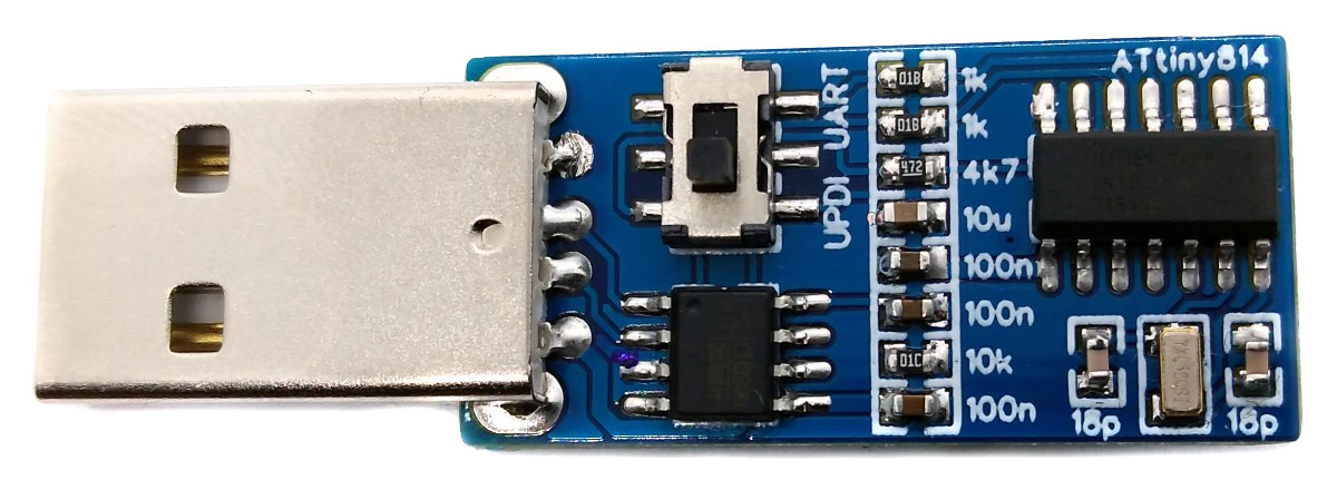
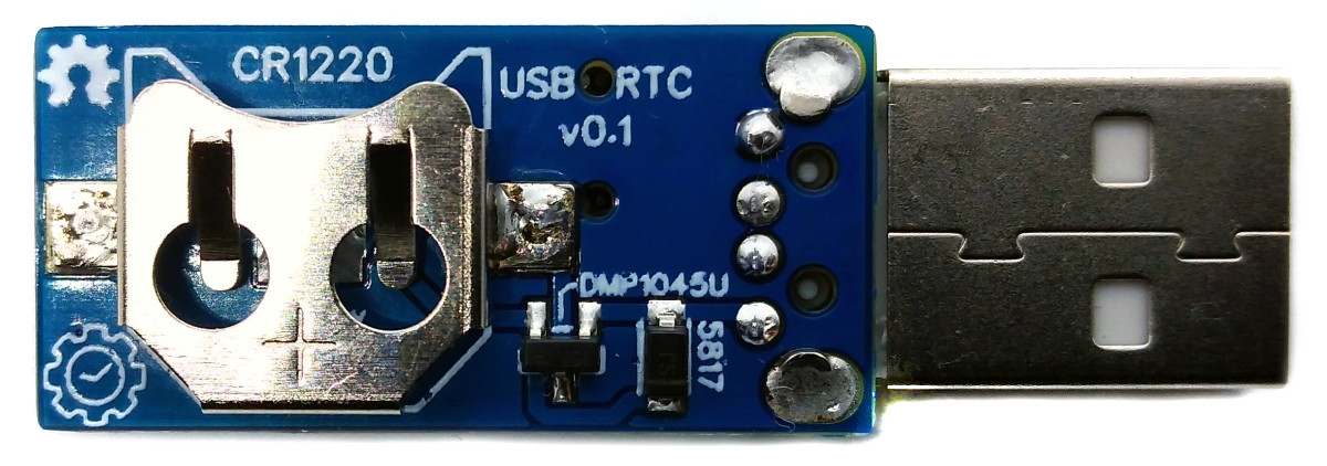
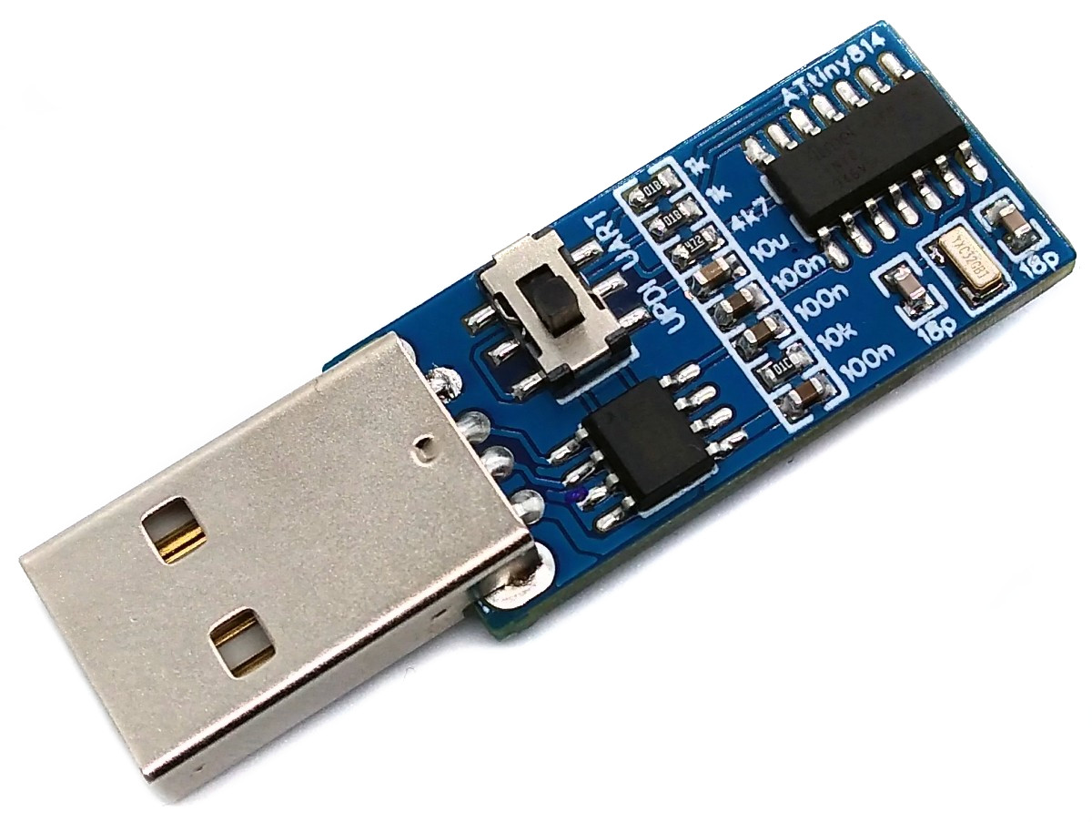
The USB-RTC is a simple real-time clock that can supply devices without one (e.g. Raspberry Pi) with the current time and date via USB. The CR1220, CR1225 or LIR1220 (recommended) backup battery keeps the clock running even without an external power supply. The built-in 32.768 kHz crystal ensures a reasonable accuracy of the clock. The on board CH340N (or CH330N) USB-to-serial adapter can also be used as a UPDI programmer, so that no external programming device is required. This makes the USB-RTC also suitable as a development board for RTC applications based on the new tinyAVR or megaAVR microcontrollers.
The wiring is pretty simple:
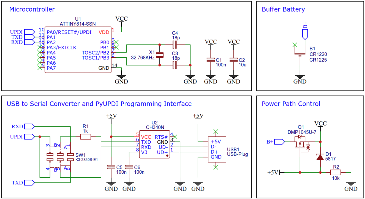
The power path control ensures that the battery is disconnected as soon as the device is supplied with power via USB. By using a MOSFET, the battery can supply the ATtiny with almost no voltage drop when no power is available via USB. The CH340N can be replaced by a CH330N. With the toggle switch the user can select UART mode for data transfer or UPDI mode for programming the device. C3/C4 are calculated for a crystal with a load capacitance (CL) of 12.5pF (C3 = C4 = 2 * CL - 7pF).
In order to make the RTC tick, the external 32.768 kHz crystal must first be selected as the clock source. Then the Periodic Interrupt Timer (PIT) is started with a prescaler of 32768, which triggers an interrupt exactly once per second and wakes the ATtiny from sleep. The clock is then advanced by one second in the main routine. For more information on the RTC refer to Microchip Technical Brief TB3213.
// Setup external 32.768 kHz crystal and periodic interrupt timer (PIT)
void RTC_init(void) {
  _PROTECTED_WRITE(CLKCTRL_XOSC32KCTRLA, CLKCTRL_ENABLE_bm); // enable crystal
  RTC.CLKSEL      = RTC_CLKSEL_TOSC32K_gc;    // select external 32K crystal
  RTC.PITINTCTRL  = RTC_PI_bm;                // enable periodic interrupt
  RTC.PITCTRLA    = RTC_PERIOD_CYC32768_gc    // set period to 1 second
                  | RTC_PITEN_bm;             // enable PIT
}

// Interrupt service routine for PIT (wake up from sleep every second)
ISR(RTC_PIT_vect) {
  RTC.PITINTFLAGS = RTC_PI_bm;                // clear interrupt flag
}The time and date functions surprisingly take care of the time and date. When the firmware is uploaded, the time is automatically set to the current time (compilation time). The time and date are updated every second, triggered by the Periodic Interrupt Timer (PIT). Leap years are taken into account and weekdays are calculated. For more information on the relevant calculations, see Microchip Application Note AN2543 and Sakamoto's method on wikipedia.
// Returns TRUE if year is NOT a leap year (refer to AN2543)
uint8_t TIME_notLeapYear(void) {
  if (!(t.year % 100)) return (t.year % 400);
  return (t.year % 4);
}

// Returns day of the week (Sakamoto's method, refer to wikipedia)
uint8_t TIME_dayOfTheWeek(void) {
  static uint8_t td[] = {0, 3, 2, 5, 0, 3, 5, 1, 4, 6, 2, 4};
  uint16_t y = t.year;
  if (t.month < 3) y -= 1;
  return (y + y/4 - y/100 + y/400 + td[t.month - 1] + t.day) % 7;
}The new tinyAVR are equipped with a hardware module for UART, so implementation is very easy. The internal oscillator is sufficiently accurate. The optional calibration with regard to the supply voltage was omitted here. Since the crystal oscillator is attached to the standard pins for UART, the alternative UART pins must be used. For more information on the USART module refer to Microchip Technical Brief TB3216.
#define UART_BAUD       9600
#define UART_BAUD_RATE  4.0 * F_CPU / UART_BAUD + 0.5

// UART init
void UART_init(void) {
  PORTMUX.CTRLB = PORTMUX_USART0_bm;          // select alternative pins for USART0
  USART0.BAUD   = UART_BAUD_RATE;             // set BAUD
  USART0.CTRLB  = USART_TXEN_bm;              // enable TX
}

// UART transmit data byte
void UART_write(uint8_t data) {
  while (~USART0.STATUS & USART_DREIF_bm);    // wait until ready for next data
  USART0.TXDATAL = data;                      // send data byte
}

// UART print string
void UART_print(const char *str) {
  while(*str) UART_write(*str++);             // write characters of string
}

// UART print 2-digit integer value via UART
void UART_printVal(uint8_t value) {
  UART_write((value / 10) + '0');
  UART_write((value % 10) + '0');
}The power supply of the ATtiny is switched between USB and battery automatically in hardware (power path control). However, in order to work as energy-efficiently as possible in battery operation, the ATtiny must know whether it is powered by USB or battery. A simple option that does not require any additional hardware or I/O pins is to measure the supply voltage (VCC, or more correctly VDD). The voltage of the battery is always less than 4.3V, the USB voltage is always greater. To find out the supply voltage, the internal 1.1V bandgap is measured with reference to VCC by the Analog to Digital Converter (ADC). Since high accuracy is not required, an 8-bit measurement is sufficient. It should be noted that the internal bandgap needs a short time to reach its accuracy, especially after waking up from a sleep mode. Fortunately, this time can be set in the associated register so that it is automatically taken into account in the following measurements. For more information on how to measure VCC refer to Microchip Application Note AN2447.
// ADC init for VCC measurements
void ADC_init(void) {
  VREF.CTRLA  = VREF_ADC0REFSEL_1V1_gc;       // select 1.1V reference
  ADC0.MUXPOS = ADC_MUXPOS_INTREF_gc;         // set internal reference as ADC input
  ADC0.CTRLC  = ADC_REFSEL_VDDREF_gc          // set VCC as reference
              | ADC_PRESC_DIV4_gc;            // set prescaler for 1.25 MHz ADC clock
  ADC0.CTRLD  = ADC_INITDLY_DLY64_gc;         // delay to settle internal reference
  ADC0.CTRLA  = ADC_RESSEL_bm                 // select 8-bit resolution
              | ADC_ENABLE_bm;                // enable ADC, single shot
}

// ADC return TRUE if USB powered
uint8_t ADC_isUSB(void) {
  ADC0.COMMAND = ADC_STCONV_bm;               // start sampling supply voltage
  while(ADC0.COMMAND & ADC_STCONV_bm);        // wait for ADC sampling to complete
  return(ADC0.RESL < 65);                     // return TRUE if VCC > 4.3V (65=256*1.1V/4.3V)
}In order to save energy, the ATtiny spends most of its time in sleep mode power down when it is running on batteries. The Periodic Interrupt Timer (PIT), which is driven by the 32.768 kHz crystal, wakes the ATtiny once per second to update the time. In addition, all pins that are not required are switched off. For more information on power saving refer to Microchip Training Manual.
// Disable unused pins to save power
for (uint8_t pin=7; pin; pin--) (&PORTA.PIN0CTRL)[pin] = PORT_ISC_INPUT_DISABLE_gc;
PORTB.PIN0CTRL = PORT_ISC_INPUT_DISABLE_gc;
PORTB.PIN1CTRL = PORT_ISC_INPUT_DISABLE_gc;
// Prepare sleep mode
SLPCTRL.CTRLA = SLPCTRL_SMODE_PDOWN_gc // set sleep mode to power down
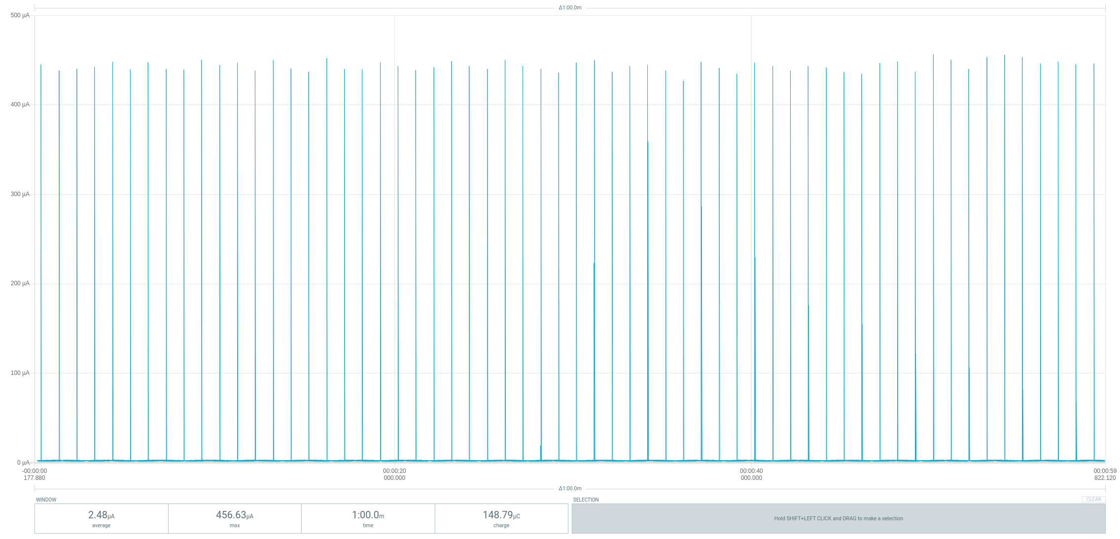
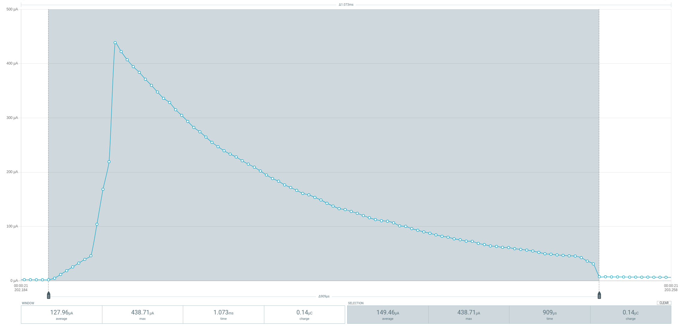
| SLPCTRL_SEN_bm; // enable sleep modeAccording to the measurements with the Power Profiler Kit II, an average current of 2.5µA at a voltage of 3V is consumed in battery operation. A typical CR1225 battery has a capacity of 50mAh. This results in a theoretical battery life of 20,000 hours or 833 days or 2.34 years. A rechargeable LIR1220 battery, on the other hand, only has a capacity of 8mAh, which leads to a service life of around 3,200 hours or 133 days. However, this is sufficient for most applications and since a LIR1220 can withstand higher current peaks, which leads to more stable operation, it is to be preferred overall.
- Install the CR1220, CR1225 or LIR1220 (recommended) buffer battery.
- Set the selector switch on the device to UPDI.
- Plug the device into a USB port of your PC.
- Open your Arduino IDE.
- Make sure you have installed megaTinyCore.
- Go to Tools -> Board -> megaTinyCore and select ATtiny1614/1604/814/804/414/404/214/204.
- Go to Tools and choose the following board options:
- Chip: ATtiny814 or ATtiny414 or ATtiny214
- Clock: 5 MHz internal
- Programmer: SerialUPDI
- Leave the rest at the default settings.
- Go to Tools -> Burn Bootloader to burn the fuses.
- Open USB-RTC sketch and click Upload.
- Set the selector switch on the device back to UART.
- Make sure you have installed the latest avr-gcc toolchain.
- Open a terminal.
- Navigate to the folder with the makefile and the Arduino sketch.
- Run
DEVICE=attiny814 make installto compile, burn the fuses and upload the firmware (change DEVICE accordingly). - Set the selector switch on the device back to UART.
The time and date of the USB-RTC are automatically set to the current time (compilation time) when the firmware is uploaded.
- Set the selector switch on the device to UART.
- Plug the device into a USB port of your PC.
- Open a serial monitor and set it to 9600 BAUD.
- ATtiny814 Datasheet
- TB3213 - Getting Started with RTC
- TB3216 - Getting Started with USART
- AN2447 - Measure VCC/Battery Voltage
- AN2543 - Temperature Logger
- ADC and Power Optimization
- Determination of the Day of the Week

This work is licensed under Creative Commons Attribution-ShareAlike 3.0 Unported License. (http://creativecommons.org/licenses/by-sa/3.0/)