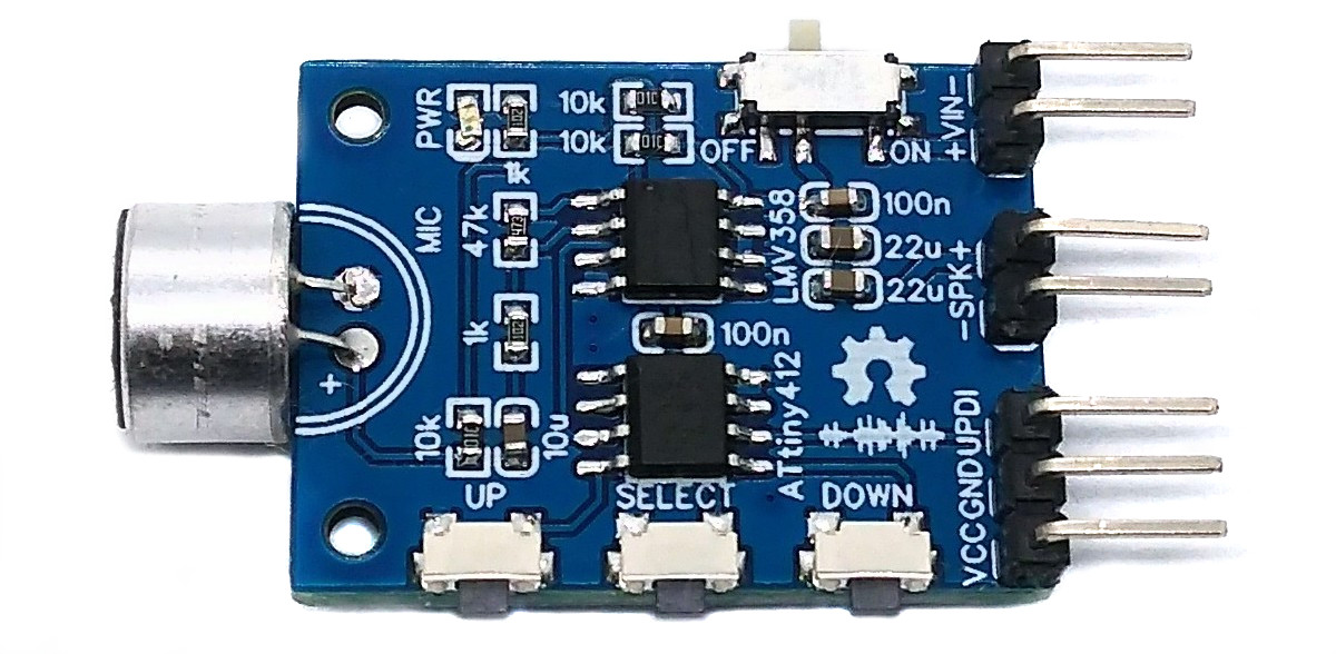
The ATtiny412 VoiceChanger is a simple device for changing the pitch of speech and other audio signals. An electret microphone is installed for audio input, and a small loudspeaker can be connected directly to the board for output.
- Design Files (EasyEDA): https://easyeda.com/wagiminator/attiny412-voice-changer
The schematic is shown below:
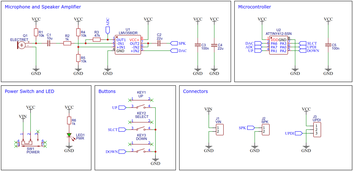
The inexpensive LMV358 rail-to-rail dual OpAmp is used to amplify the audio signals. The first OpAmp amplifies the weak signal from the electret microphone. The amplification factor is determined by resistors R2 and R3 (Gain = R3 / R2 = 47). If desired, the gain can be increased by replacing the 47k (R3) with a 100k resistor, which will also increase the output volume. The voltage divider formed by R4 and R5 at the positive input of the OpAmp defines the virtual ground and lets the audio signal oscillate around half the supply voltage. The output of the first OpAmp is connected to the ATtiny's analog-to-digital converter (ADC), which samples the amplified audio signal. This signal is modified by the ATtiny and output via its digital-to-analog converter (DAC). Since the DAC cannot drive a load directly, the signal is amplified by the LMV358's second OpAmp, which is configured as a voltage follower/buffer. The output of this OpAmp drives the speaker through a coupling capacitor (C2).
The amplified input signal is sampled by the ATtiny's ADC. For this purpose, the ADC is operated in free-running mode with a resolution of 8 bits and an ADC clock frequency of 500kHz. This results in a sampling rate of 500kHz/13 = 38kHz. After each conversion, an interrupt is triggered, in the service routine of which the sampled value is pushed into a 192-byte ring buffer.
// ===================================================================================
// Ring Buffer Implementation
// ===================================================================================

#define BUF_LEN       192                       // buffer length
volatile uint8_t BUF_buffer[BUF_LEN];           // this is the buffer
volatile uint8_t BUF_head, BUF_tail;            // head and tail pointer

// Push byte to ring buffer
void BUF_push(uint8_t data) {
  if(++BUF_head >= BUF_LEN) BUF_head = 0;       // increase head pointer
  BUF_buffer[BUF_head] = data;                  // push data byte to buffer
}

// Pop data byte from buffer
uint8_t BUF_pop(void) {
  if(++BUF_tail >= BUF_LEN) BUF_tail = 0;       // increase tail pointer
  return BUF_buffer[BUF_tail];                  // pop data byte from buffer
}

// ===================================================================================
// ADC Implementation for Audio Input
// ===================================================================================

// Init analog to digital converter (ADC)
void ADC_init(void) {
  pinDisable(PIN_ADC);                          // disable digital input buffer
  ADC0.CTRLA   = ADC_RESSEL_8BIT_gc             // 8-bit resolution
               | ADC_FREERUN_bm                 // free running mode
               | ADC_ENABLE_bm;                 // enable ADC
  ADC0.CTRLC   = ADC_SAMPCAP_bm                 // select sample capacitance
               | ADC_REFSEL_VDDREF_gc           // set Vdd as reference
               | ADC_PRESC_DIV8_gc;             // set prescaler -> 500kHz ADC clock
  ADC0.MUXPOS  = PIN_ADC;                       // set the input pin
  ADC0.INTCTRL = ADC_RESRDY_bm;                 // enable result ready interrupt
  ADC0.COMMAND = ADC_STCONV_bm;                 // start first conversion
}

// ADC result ready interrupt service routine
ISR(ADC0_RESRDY_vect) {
  BUF_push(ADC0.RESL);                          // push result to buffer
}
The timer/counter B (TCB) is set up in such a way that it periodically triggers another interrupt, in the service routine of which a value is pulled from the ring buffer and written to the data register of the DAC. The frequency of these interrupts can be changed using the keys. If the frequency of the timer interrupts is equal to the ADC sampling frequency (38kHz), the output signal also corresponds to the input signal. If the frequency of the timer interrupt is higher than the sampling frequency of the ADC, the pitch of the audio signal will be increased and vice versa.
// ===================================================================================
// DAC Implementation for Audio Output
// ===================================================================================

// Setup the digital to analog converter (DAC)
void DAC_init(void) {
  pinDisable(PIN_DAC);                          // disable digital input buffer
  VREF_CTRLA |= VREF_DAC0REFSEL_4V34_gc;        // set DAC reference to 4.3V
  DAC0.CTRLA  = DAC_ENABLE_bm                   // enable DAC
              | DAC_OUTEN_bm;                   // enable output buffer
}

// Set DAC value
void DAC_set(uint8_t value) {
  DAC0.DATA = value;                            // set DAC
}

// ===================================================================================
// Periodic Interrupt Implementation using TCB for Audio Output
// ===================================================================================

// Init timer/counter B (TCB)
void TCB_init(void) {
  TCB0.CTRLA   = TCB_CLKSEL_CLKDIV1_gc          // set prescaler
               | TCB_ENABLE_bm;                 // enable timer
  TCB0.CTRLB   = TCB_CNTMODE_INT_gc;            // set timer to periodic interrupt mode
  TCB0.CCMP    = PITCH_START;                   // set TOP value
  TCB0.INTCTRL = TCB_CAPT_bm;                   // enable interrupt
}

// Set pitch value
void TCB_setPitch(uint8_t value) {
  TCB0.CCMP = value;                            // set pitch value
  TCB0.CNT  = 0;                                // reset counter
}

// Timer interrupt service routine
ISR(TCB0_INT_vect) {
  TCB0.INTFLAGS = TCB_CAPT_bm;                  // clear interrupt flag
  DAC_set(BUF_pop());                           // set DAC value from buffer
}- Open your Arduino IDE.
- Make sure you have installed megaTinyCore.
- Go to Tools -> Board -> megaTinyCore and select ATtiny412/402/212/202.
- Go to Tools and choose the following board options:
- Chip: ATtiny412
- Clock: 4 MHz internal
- Leave the rest at the default settings.
- Connect your programmer to your PC and to the UPDI header on the board.
- Go to Tools -> Programmer and select your UPDI programmer.
- Go to Tools -> Burn Bootloader to burn the fuses.
- Open the sketch and click Upload.
- Connect your programmer (jtag2updi or SerialUPDI) to your PC and to the UPDI header on the board.
- Make sure you have installed the latest avr-gcc toolchain.
- Open a terminal.
- Navigate to the folder with the makefile and the sketch.
- Run
PROGRMR=serialupdi PORT=/dev/ttyUSB0 make installto compile, burn the fuses and upload the firmware (change PROGRMR and PORT accordingly).
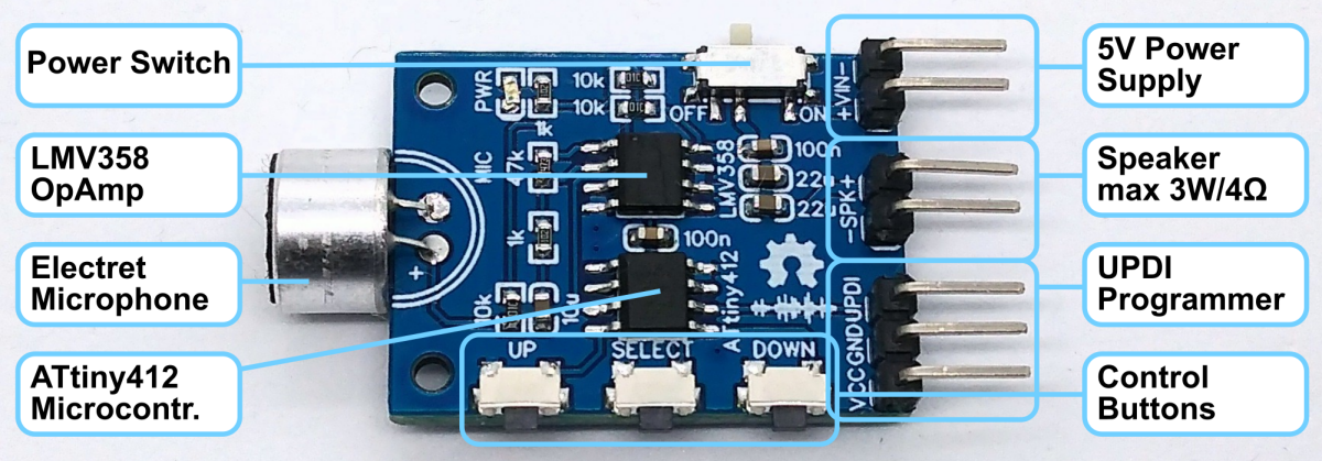
- Connect a 5V power supply to the respective header on the board. Pay attention to the correct polarity!
- Connect a little speaker (max 3W/4Ω) to the respective header.
- Turn on the switch and speak into the microphone.
- Use the buttons to modify the pitch.

This work is licensed under Creative Commons Attribution-ShareAlike 3.0 Unported License. (http://creativecommons.org/licenses/by-sa/3.0/)