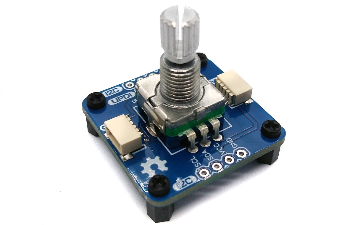
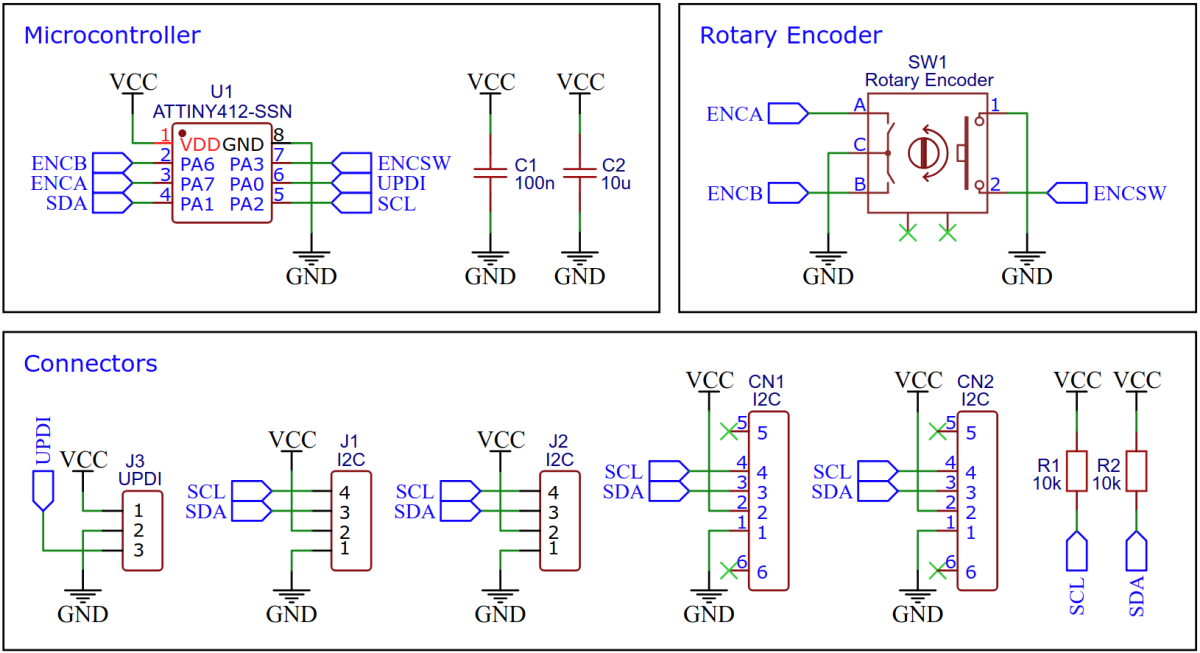
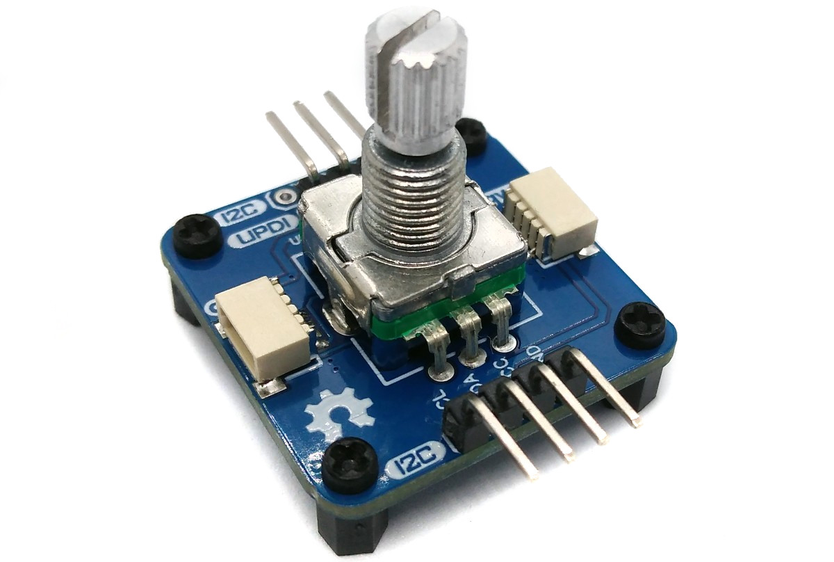
Rotary encoders are a nice touch for many projects. However, their control requires some pins, interrupts and debouncing. Thanks to this device, a rotary encoder can be easily controlled via the I²C interface, the built-in ATtiny202/212/402/412 does the rest. By assigning different I²C addresses, it is even possible to daisy-chain several rotary encoders. The device is powered via the I²C connection and operates in the voltage range between 2.7V and 5V.
- Design Files (EasyEDA): https://easyeda.com/wagiminator/attiny412-i2c-rotary-encoder
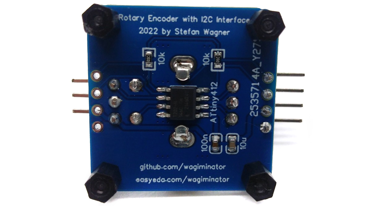
The heart of the firmware is the I²C slave implementation. Since the ATtiny supports this in hardware, things are pretty easy. A simple register array is used to read and write the rotary encoder parameters and states. Data transmission and reception are handled via interrupts.
// I2C slave command macros
#define I2C_complete() TWI0.SCTRLB = TWI_SCMD_COMPTRANS_gc
#define I2C_response() TWI0.SCTRLB = TWI_SCMD_RESPONSE_gc
#define I2C_sendACK()  TWI0.SCTRLB = TWI_ACKACT_ACK_gc  | TWI_SCMD_RESPONSE_gc
#define I2C_sendNACK() TWI0.SCTRLB = TWI_ACKACT_NACK_gc | TWI_SCMD_RESPONSE_gc
#define I2C_put(x)     TWI0.SDATA  = (x)
#define I2C_get()      TWI0.SDATA

// I2C slave status macros
#define I2C_isAddr()  ((TWI0.SSTATUS & TWI_APIF_bm) && (TWI0.SSTATUS & TWI_AP_bm))
#define I2C_isData()  (TWI0.SSTATUS & TWI_DIF_bm)
#define I2C_isStop()  ((TWI0.SSTATUS & TWI_APIF_bm) && (~TWI0.SSTATUS & TWI_AP_bm))
#define I2C_isIn()    (~TWI0.SSTATUS & TWI_DIR_bm)
#define I2C_isOut()   (TWI0.SSTATUS & TWI_DIR_bm)

// I2C slave registers
uint8_t I2C_REG[10];                              // register array
uint8_t I2C_REG_ptr;                              // register pointer
volatile uint8_t I2C_REG_changed = 0;             // register change flag
volatile uint8_t I2C_busy = 0;                    // I2C busy flag

// I2C slave init
void I2C_init(void) {
  TWI0.SADDR  = I2C_ADDR << 1;                    // set address (LSB is R/W bit)
  TWI0.SCTRLA = TWI_DIEN_bm                       // data interrupt enable
              | TWI_APIEN_bm                      // address or stop interrupt enable
              | TWI_PIEN_bm                       // stop interrupt enable
              | TWI_ENABLE_bm;                    // enable I2C slave
}

// I2C slave interrupt service routine
ISR(TWI0_TWIS_vect) {
  // Address match interrupt handler
  if(I2C_isAddr()) {                              // address match?
    I2C_sendACK();                                // send ACK to master
    I2C_REG_ptr = 0;                              // reset register pointer
    I2C_busy = 1;                                 // set I2C busy flag
    return;                                       // quit ISR
  }

  // Data interrupt handler
  if(I2C_isData()) {                              // data transmission?
    if(I2C_isOut()) {                             // slave writing to master?
      I2C_put(I2C_REG[I2C_REG_ptr]);              // send register value to master
      I2C_response();                             // no ACK needed here
    } else {                                      // slave reading from master?
      I2C_REG[I2C_REG_ptr] = I2C_get();           // read register value from master
      I2C_sendACK();                              // send ACK to master
      I2C_REG_changed = 1;                        // set register changed flag
    }
    if(++I2C_REG_ptr >= sizeof(I2C_REG))          // increase pointer...
      I2C_REG_ptr = 0;                            // ...or wrap around
    return;                                       // quit ISR
  }

  // Stop condition interrupt handler
  if(I2C_isStop()) {                              // stop condition?
    I2C_complete();                               // complete transaction
    I2C_busy = 0;                                 // clear I2C busy flag
  }
}
The I²C address of the device can be set in the firmware parameters at the beginning of the code.
// Firmware parameters
#define I2C_ADDR 0x36 // I2C address of the device- Open your Arduino IDE.
- Make sure you have installed megaTinyCore.
- Go to Tools -> Board -> megaTinyCore and select ATtiny412/402/212/202.
- Go to Tools and choose the following board options:
- Chip: Choose the chip that is installed on your device
- Clock: 10 MHz internal
- Leave the rest at the default settings.
- Connect your programmer to your PC and to the UPDI header on the board.
- Go to Tools -> Programmer and select your UPDI programmer.
- Go to Tools -> Burn Bootloader to burn the fuses.
- Open the sketch and click Upload.
- Make sure you have installed the latest avr-gcc toolchain.
- Open a terminal.
- Navigate to the folder with the makefile and the sketch.
- Run
DEVICE=attiny412 PROGRMR=serialupdi PORT=/dev/ttyUSB0 make installto compile, burn the fuses and upload the firmware (change DEVICE, PROGRMR and PORT accordingly).
The device has four 16-bit and two 8-bit registers that can be read and written. The 16-bit registers are signed and the least significant byte is always transmitted first. With each access (reading or writing), the registers are always transferred starting with the first in the following order:
- Encoder wheel value (16-bit)
- Encoder switch state (8-bit, 0=switch released, 1=switch pressed)
- Encoder wheel value loop flag (8-bit, 0=do not loop, 1=loop around)
- Encoder wheel minimum value (16-bit)
- Encoder wheel maximum value (16-bit)
- Encoder wheel value change step (16-bit)
An example code for controlling the device is attached. It uses the standard Arduino Wire library, so it should run on almost all supported microcontrollers.
#include <Wire.h>

#define encoder_addr 0x36

int16_t value, lastvalue;
boolean pressed, lastpressed;

void setup() {
  Serial.begin(9600);
  Wire.begin();
  encoder_set(-50, 50, 1, 0, 0);
}

void loop() {
  value = encoder_getValue();
  if(value != lastvalue) {
    Serial.println(value);
    lastvalue = value;
  }
  pressed = encoder_isPressed();
  if(pressed != lastpressed) {
    if(pressed) Serial.println("Switch was pressed");
    lastpressed = pressed;
  }
  delay(20);
}

// Set encoder wheel parameters
void encoder_set(int16_t rmin, int16_t rmax, int16_t rstep, int16_t rval, uint8_t rloop) {
  Wire.beginTransmission(encoder_addr);
  Wire.write((uint8_t)(rval & 0xff)); Wire.write((uint8_t)(rval >> 8));
  Wire.write(0); Wire.write(rloop);
  Wire.write((uint8_t)(rmin & 0xff)); Wire.write((uint8_t)(rmin >> 8));
  Wire.write((uint8_t)(rmax & 0xff)); Wire.write((uint8_t)(rmax >> 8));
  Wire.write((uint8_t)(rstep & 0xff)); Wire.write((uint8_t)(rstep >> 8));
  Wire.endTransmission();
}

// Set encoder wheel value
void encoder_setValue(int16_t rval) {
  Wire.beginTransmission(encoder_addr);
  Wire.write((uint8_t)(rval & 0xff)); Wire.write((uint8_t)(rval >> 8));
  Wire.endTransmission();
}

// Read encoder wheel value
int16_t encoder_getValue() {
  Wire.requestFrom(encoder_addr, 2);
  return((uint16_t)Wire.read() | ((uint16_t)Wire.read() << 8));
}

// Read encoder switch state
boolean encoder_isPressed() {
  Wire.requestFrom(encoder_addr, 3);
  Wire.read(); Wire.read();
  return(Wire.read());
}

This work is licensed under Creative Commons Attribution-ShareAlike 3.0 Unported License. (http://creativecommons.org/licenses/by-sa/3.0/)