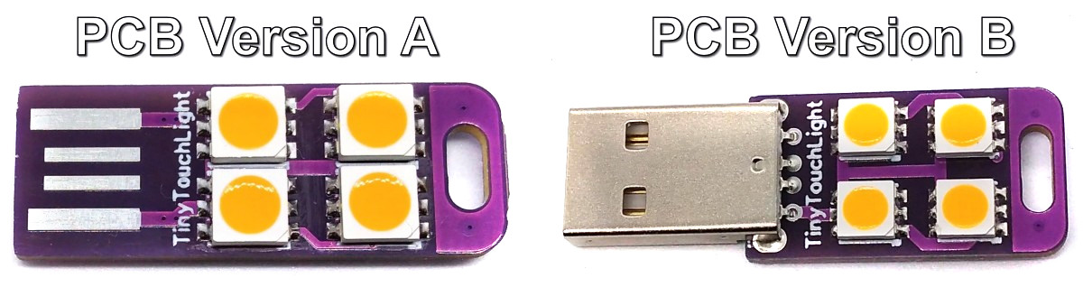
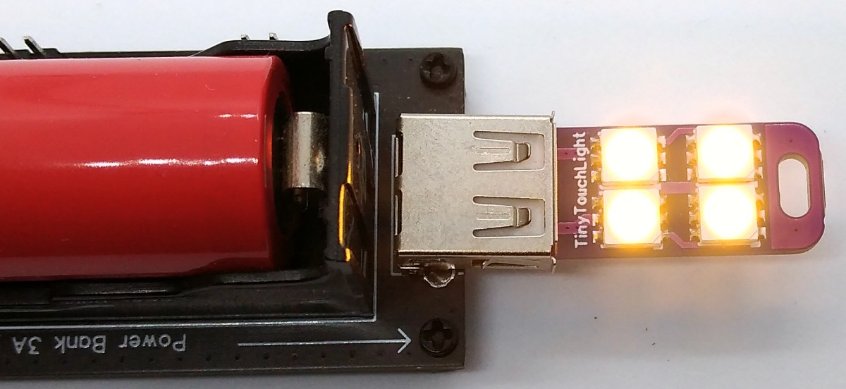
TinyTouchLight is a dimmable USB night light with capacitive touch control based on the ATtiny13A. It plugs into any USB charger or power bank.
- Project Video (YouTube): https://youtu.be/TYuayp2b2vI
- Design Files (EasyEDA): https://easyeda.com/wagiminator/attiny13-tinytouchlight_copy
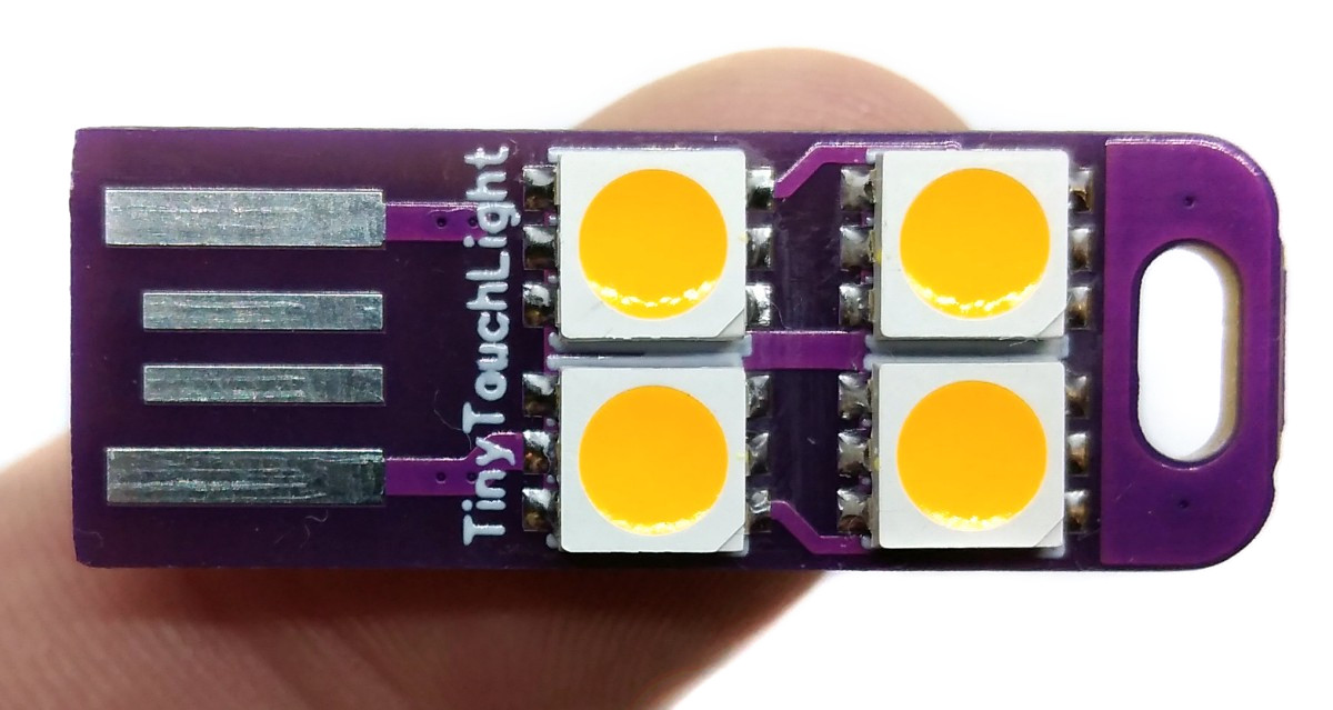
This implementation of a touch-sensitive button (touchkey) is based on the charge sharing approach similar to Atmel's QTouchADC and Tim's TinyTouchLib. It works without external components, only a resistor for noise reduction is used, which can also be dispensed with. The touchkey itself is a small copper area on the PCB (sense electrode), which is covered with solder mask. This sense electrode is connected to a single ADC-capable pin of the ATtiny via the resistor.
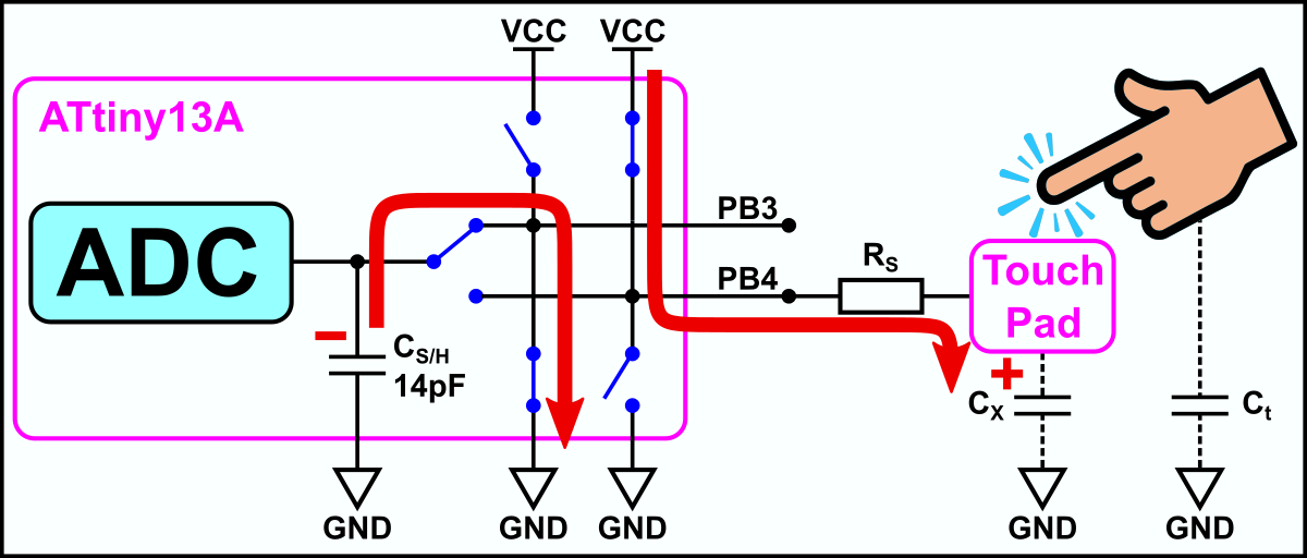
The touch sense pin (here PB4) is connected through series resistor RS to the sensor electrode capacitance, represented by Cx. The switch SW represents a finger touching the key. The capacitance introduced by the finger is represented as Ct. When the key is touched, Ct is switched into the circuit forming a parallel capacitor with Cx, changing the effective sensor capacitance to Cx + Ct.
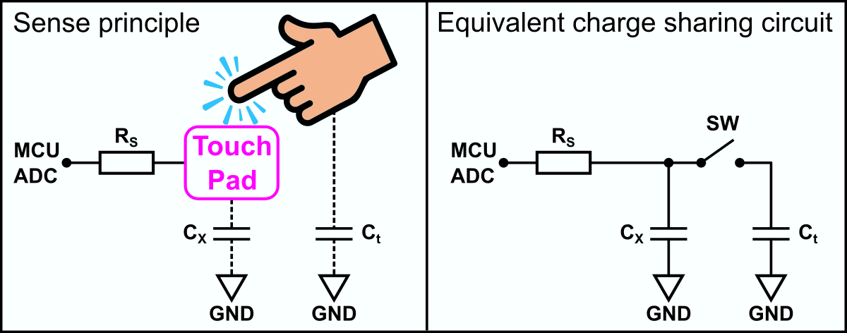
It should be noted that Cx and Ct are not physical capacitors. Cx is the effective capacitance of the sense electrode and Cx + Ct is the effective capacitance of the human finger touching the sensor.
The series resistor RS is nominally 1kΩ, but it may be increased to higher values to improve the noise immunity of the circuit. The value of RS should be increased in steps to find the lowest value that provides adequate noise immunity. Resistance values of up to 100kΩ have proven to be useful in extremely noisy environments. For this application a 47kΩ resistor was chosen.
The value of Cx should be close to that of the ADC’s internal sample-and-hold capacitor CS/H (~14pF). For best performance it is recommended that Cx+t should not be greater than ~60pF. If the sensor electrode is designed as a copper surface on the PCB, then it should be roughly as large as the contact surface of a finger (8-15 mm in diameter if the touchkey sensor is round, or with a 8-15 mm side if the touchkey sensor is square). There shouldn't be any traces on the other side of the PCB. The back side can have a ground plane, but this should not be a solid fill.
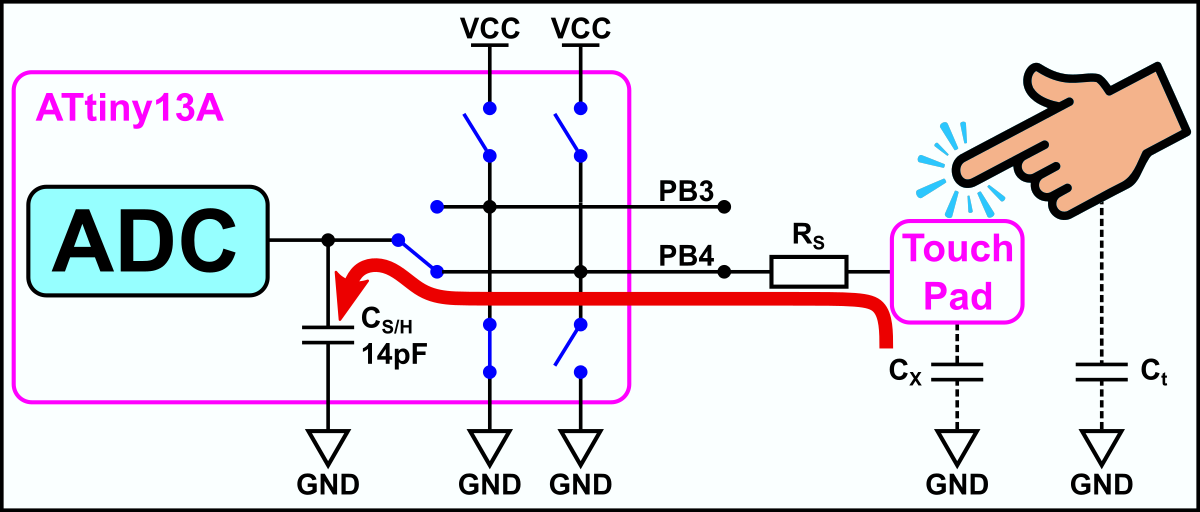
The acquisition method works by sharing charge between the ADC’s internal sample-and-hold capacitor (CS/H) and the sense electrode capacitance (Cx). When the sensor is touched the effective capacitance of the sensor electrode increases and becomes Cx + Ct. This affects the amount of charge shared between the capacitors. When pre-charging Cx and sharing with CS/H, charge transferred to CS/H increases on touch and ADC input voltage increases. When pre-charging CS/H and sharing with Cx, charge remaining on CS/H decreases on touch and ADC input voltage decreases. But the resulting signal from the averaged ADC values increases on touch. If the difference between signal and reference is greater than the user-determined threshold (delta), a touch is reported.
The charge sharing is carried out in the following sequence:
- Precharge touchkey LOW and S/H cap HIGH.
- Connect touchkey and S/H cap in parallel. Read the voltage via the ADC.
- Precharge touchkey HIGH and S/H cap LOW.
- Connect touchkey and S/H cap in parallel. Read the voltage via the ADC.
- Calculate the voltage difference and compare it with the user-determined threshold.
By setting the touch sense pin (PB4) to OUTPUT LOW, the touchkey is discharged. By setting the ADC muxer to a spare pin (here PB3) and setting this pin to OUTPUT HIGH, the internal S/H capacitor is charged.
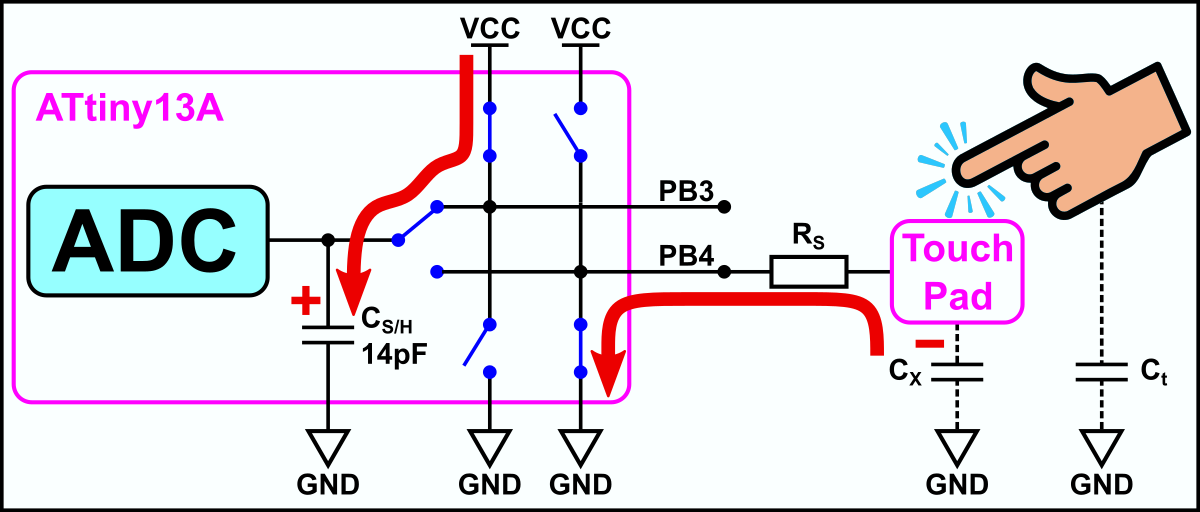
ADMUX   =  TC_SHC_ADC;              // connect spare pin to S/H cap
PORTB  |=  (1<<TC_SHC_PIN);         // charge S/H cap
PORTB  &= ~(1<<TC_PAD_PIN);         // prepare discharge touch pad
DDRB   |=  (1<<TC_PAD_PIN);         // discharge touch pad
_delay_us(TC_CHARGETIME); // wait for precharge completeBy setting the touch sense pin (PB4) to INPUT (no pullup) and setting the ADC muxer to this pin, charge is flowing between the capacitors until the charge is distributed proportionally between them - the charge is shared. The voltage across CS/H, due to the remaining charge, is sampled by the ADC.
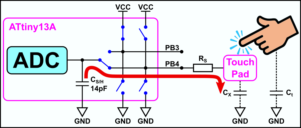
DDRB   &= ~(1<<TC_PAD_PIN);         // float pad input (pull up is off)
ADMUX   =  (1<<ADLAR) | TC_PAD_ADC; // connect touch pad to S/H and ADC
ADCSRA |=  (1<<ADSC)  | (1<<ADIF);  // start voltage sampling
while (!(ADCSRA & (1<<ADIF)));      // wait for sampling complete
uint8_t dat1 = ADCH; // read sampling result (voltage)By setting the touch sense pin (PB4) to OUTPUT HIGH, the touchkey is scharged, by setting the the ADC muxer to the spare pin (PB3) and setting this pin to OUTPUT HIGH, the internal S/H capacitor is discharged.
ADMUX   =  TC_SHC_ADC;              // connect spare pin to S/H cap
PORTB  &= ~(1<<TC_SHC_PIN);         // discharge S/H cap
PORTB  |=  (1<<TC_PAD_PIN);         // prepare charge touch pad
DDRB   |=  (1<<TC_PAD_PIN);         // charge touch pad
_delay_us(TC_CHARGETIME); // wait for precharge completeBy setting the touch sense pin (PB4) to INPUT (no pullup) and setting the ADC muxer to this pin, charge is flowing between the capacitors until the charge is distributed proportionally between them - the charge is shared again. The resulting voltage is sampled by the ADC.
DDRB   &= ~(1<<TC_PAD_PIN);         // float touch pad input
PORTB  &= ~(1<<TC_PAD_PIN);         // pull up off
ADMUX   =  (1<<ADLAR) | TC_PAD_ADC; // connect touch pad to S/H and ADC
ADCSRA |=  (1<<ADSC)  | (1<<ADIF);  // start voltage sampling
while (!(ADCSRA & (1<<ADIF)));      // wait for sampling complete
uint8_t dat2 = ADCH; // read sampling result (voltage)The measured and calculated voltage difference is returned by the function TC_getDelta(), which includes the code shown above. The function TC_sense() averages 16 of these measurements, calculates the difference with the non-touch bias and compares this difference with the user-defined thresholds. It also makes sure that there is no drift or stuck button. The function returns a value which represents if the touchkey is pressed, released or hold.
uint8_t TC_sense(void) {
  uint16_t tmp = 0;
  for (uint8_t i=16; i; i--) {
    tmp += TC_getDelta();             // average 16 samples
    _delay_us(100);
  }
  int16_t diff = tmp - (TC_bias>>4);  // difference with bias value
  if (!TC_touch) {                    // not touched previously?
    if (diff > TC_THRESHOLD_ON) {     // new touch detected?
      TC_touch = 1;                   // set "is touched" flag
      TC_timer = 0;                   // reset touch timer
      return TC_PUSH;                 // return "new push"
    }
    TC_bias = (TC_bias - (TC_bias>>6)) + (tmp>>2); // update bias (low pass)
    return TC_OFF;                    // return "still not pushed"
  }
  else {                              // touched previously?
    if (diff < TC_THRESHOLD_OFF) {    // touch button released?
      TC_touch = 0;                   // clear "is touched" flag
      return TC_RELEASE;              // return "touch pad released"
    }
    if (TC_timer == TC_TIMEOUT) {     // still touched but for too long?
      TC_bias  = TC_getDelta()<<8;    // maybe stuck situation, read new bias
      return TC_FAIL;                 // return "fail"
    }
    TC_timer++;                       // increase timer
    return TC_ON;                     // return "still pushed"
  }
}The LEDs are controlled via a PWM-capable pin (PB0) and a MOSFET. Timer0 generates the PWM signal, the duty cycle is controlled via the OCR0A register. The main function brings everything together:
int main(void) {
  // Local variables
  uint8_t bright = 64;                // current brightness of LEDs
  uint8_t dir    = 0;                 // current fade direction

  // Setup
  TCCR0A = (1<<COM0A1)                // clear OC0A on compare match, set at TOP
         | (1<<WGM01) | (1<<WGM00);   // fast PWM
  TCCR0B = (1<<CS00);                 // start timer without prescaler
  DDRB   = (1<<LED_PIN);              // set LED pin as output
  TC_init();                          // setup touch control

  // Loop
  while(1) {
    uint8_t sense = TC_sense();       // read touch pad
    if(sense == TC_PUSH) dir = !dir;  // change fade direction on new push
    if(sense == TC_ON) {              // fade on touch hold
      if(dir) {                       // fade in?
        if (bright < 196) bright++;   // increase brightness
      }
      else {                          // fade out?
        if (bright) bright--;         // decrease brightness
      }
    }
    OCR0A = bright;                   // set brightness (PWM)
  }
}Since there is no ICSP header on the board, you have to program the ATtiny either before soldering using an SOP adapter, or after soldering using an EEPROM clip. The AVR Programmer Adapter can help with this.
- Make sure you have installed MicroCore.
- Go to Tools -> Board -> MicroCore and select ATtiny13.
- Go to Tools and choose the following board options:
- Clock: 128 kHz internal osc.
- BOD: disabled
- Timing: Micros disabled
- Connect your programmer to your PC and to the ATtiny.
- Go to Tools -> Programmer and select your ISP programmer (e.g. USBasp).
- Go to Tools -> Burn Bootloader to burn the fuses.
- Open the TinySat sketch and click Upload.
- Make sure you have installed avrdude.
- Connect your programmer to your PC and to the ATtiny.
- Open a terminal.
- Navigate to the folder with the hex-file.
- Execute the following command (if necessary replace "usbasp" with the programmer you use):
avrdude -c usbasp -p t13 -U lfuse:w:0x3b:m -U hfuse:w:0xff:m -U flash:w:tinytouchlight.hex
- Make sure you have installed avr-gcc toolchain and avrdude.
- Connect your programmer to your PC and to the ATtiny.
- Open a terminal.
- Navigate to the folder with the makefile and the sketch.
- Run
PROGRMR=usbasp make installto compile, burn the fuses and upload the firmware (change PROGRMR accordingly).
- Tim's TinyTouchLib
- AVR3001: QTouchADC
- AN2934: Capacitive Touch Sensor Design Guide
- ATtiny13A Datasheet

This work is licensed under Creative Commons Attribution-ShareAlike 3.0 Unported License. (http://creativecommons.org/licenses/by-sa/3.0/)