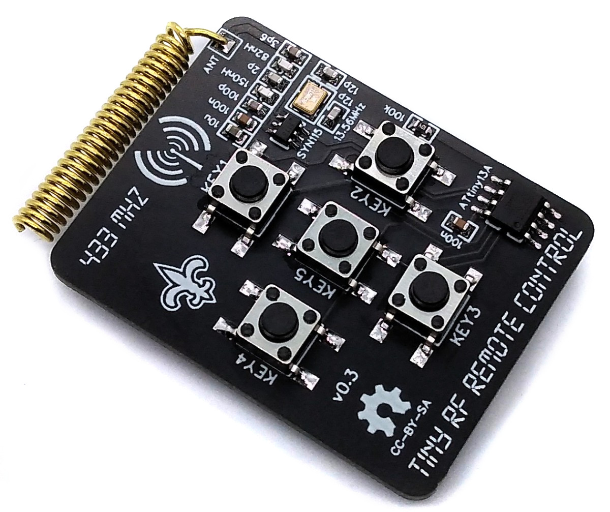
TinyRemoteRF is an RF remote control based on an ATtiny13A microcontroller and a SYN115 ASK transmitter IC powered by a CR2032 coin cell battery.
- Design Files (EasyEDA): https://easyeda.com/wagiminator/attiny13-tinyremote-rf
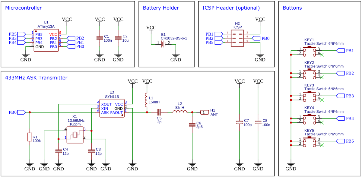
The wiring is shown below:
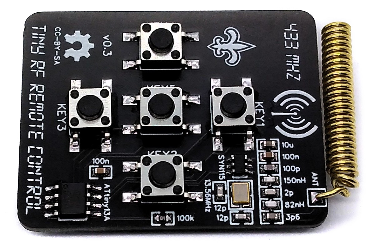
If you want to use only four buttons, you can leave KEY5 unsoldered and upload the 4-button version of the firmware. If you want to use all five buttons, you have to disable RESET on PB5 by burning the respective fuses after uploading the 5-button version of the firmware:
avrdude -c usbasp -p t13 -U lfuse:w:0x2a:m -U hfuse:w:0xfe:m
Warning: You will need a high voltage fuse resetter to undo this change!
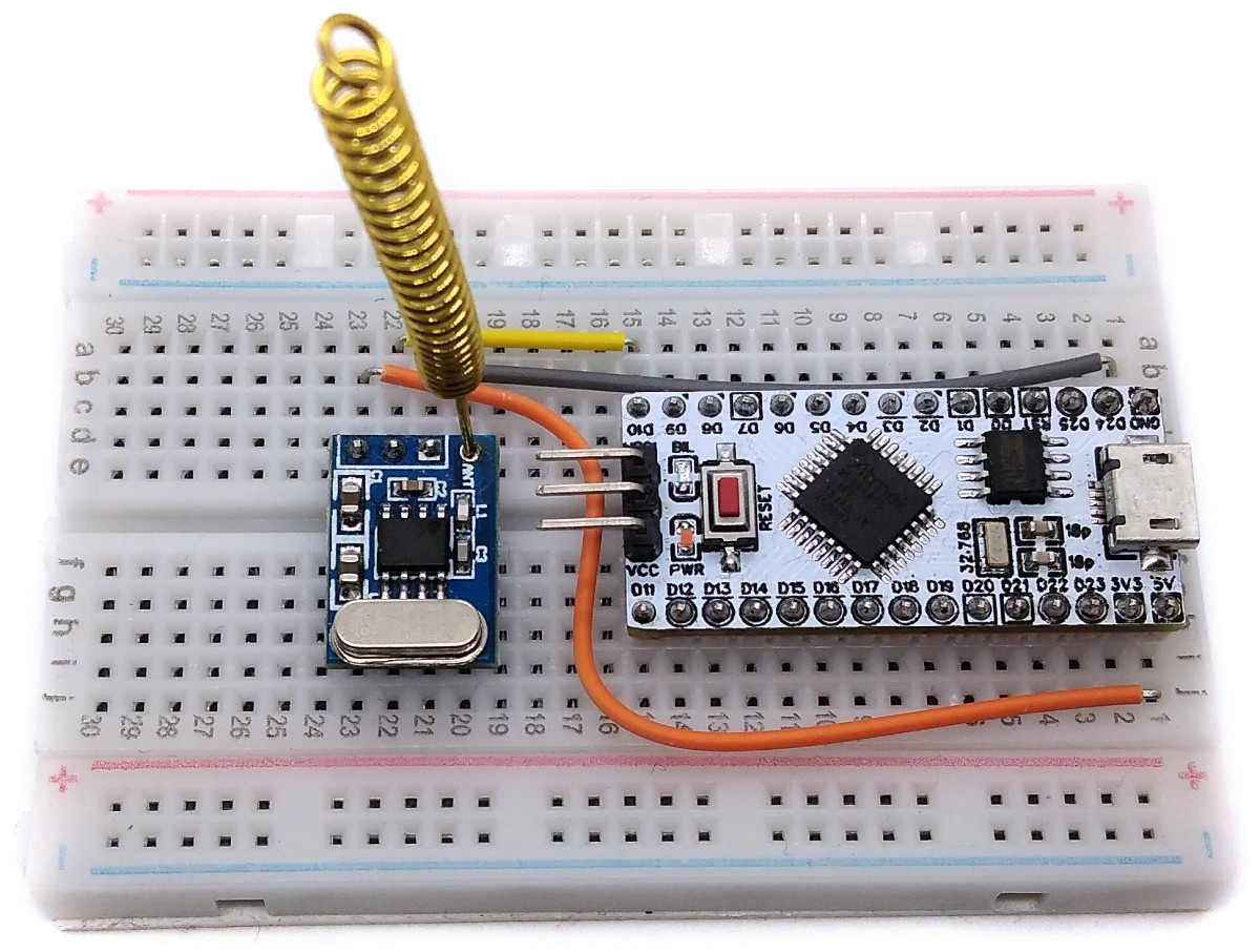
For a simple breadboard test you can directly connect the DATA pin of an RF module to PB0.
The protocol is based on the ones used for infrared remote controls, but also takes into account the special needs of a stable radio connection. It is a simple but robust and DC-free protocol which is easy to decode and does not require precise timing. It operates with ASK/OOK (Amplitude Shift Keying / On-Off Keyed).
Pulse lengths are derived from an adjustable error width (RF_ERR). A "0" bit is a 2 * RF_ERR long burst and an equally long space, a "1" bit is a 4 * RF_ERR long burst and an equally long space. A start bit is a 6 * RF_ERR long burst and an equally long space.
  +-------+       +---+   +-----+     +---+   +-  ON
  |       |       |   |   |     |     |   |   |        start:  6 * ERR
  |   6   |   6   | 2 | 2 |  4  |  4  | 2 | 2 |   ...  bit0:   2 * ERR
  |       |       |   |   |     |     |   |   |        bit1:   4 * ERR
--+       +-------+   +---+     +-----+   +---+   OFF

  |<--- start --->|<-"0"->|<---"1"--->|<-"0"->|
An RF telegram starts with the preamble in which a defined number of "0" bits are transmitted to wake up the receiver and allow it to set its automatic gain (AGC). The following start bits signify the start of the transmission. Afterwards three data bytes are transmitted, most significant bit first. The three data bytes are in order:
- the 8-bit address of the device,
- the 8-bit key-dependent command and
- the 8-bit logical inverse of the command.
After the last bit a space of at least 8 * RF_ERR signifies the end of the transmission. The transmission can be repeated several times.
At the beginning of the code, the framework conditions are set, some of which can also be adapted by the user.
// RF Codes
#define ADDR    0x55  // address of the device
#define CMD1    0x01  // command KEY1
#define CMD2    0x02  // command KEY2
#define CMD3    0x03  // command KEY3
#define CMD4    0x04  // command KEY4
#define CMD5    0x05  // command KEY5

// define RF error width in microseconds; must be the same in the receiver code;
// higher values reduce the error rate, but lengthen the transmission time
#define RF_ERR    150

// define number of preamble bits
#define RF_PRE    32

// define number of start bits; must be the same in the receiver code
#define RF_START  4

// define number of transmission repeats
#define RF_REP    3

// macros ASK/OOK
#define RF_on()   PORTB |=  (1<<DATA)   // key-on
#define RF_off()  PORTB &= ~(1<<DATA)   // key-off

// macros to modulate the signals with compensated timings
#define startPulse()  {RF_on(); _delay_us(6*RF_ERR); RF_off(); _delay_us(6*RF_ERR-5);}
#define bit0Pulse()   {RF_on(); _delay_us(2*RF_ERR); RF_off(); _delay_us(2*RF_ERR-5);}
#define bit1Pulse()   {RF_on(); _delay_us(4*RF_ERR); RF_off(); _delay_us(4*RF_ERR-5);}
#define stopPause()   _delay_us(6*RF_ERR) // = min 8 * RF_ERR incl. delay of last bit
The function for sending the RF telegram is quite simple:
// send complete telegram (preamble + start frame + address + command) via RF
void sendCode(uint8_t cmd) {
  uint8_t i, j;                           // counting variables
  for(i=RF_PRE;i;i--) bit0Pulse();        // send preamble
  for(i=RF_REP;i;i--) {                   // transmission repeat counter
    for(j=RF_START;j;j--) startPulse();   // signify start of transmission
    sendByte(ADDR);                       // send address byte
    sendByte(cmd);                        // send command byte
    sendByte(~cmd);                       // send inverse of command byte
    stopPause();                          // signify end of transmission
  }
}The code shuts down unused peripherals and utilizes the sleep mode power down function. It wakes up on every button press by pin change interrupt. The device will work several months on a CR2032 battery.
  // setup pin change interrupt
  GIMSK = (1<<PCIE);                      // turn on pin change interrupts
  PCMSK = (BT_MASK);                      // turn on interrupt on button pins
  sei();                                  // enable global interrupts

  // disable unused peripherals and set sleep mode to save power
  ADCSRA = 0;                             // disable ADC
  ACSR   = (1<<ACD);                      // disable analog comperator
  PRR    = (1<<PRTIM0) | (1<<PRADC);      // shut down ADC and timer0
set_sleep_mode(SLEEP_MODE_PWR_DOWN); // set sleep mode to power downThe accuracy of the internal oscillator of the ATtiny13 is +/-10% with the factory calibration. Usually this is sufficient for an RF remote control. Slight deviations in timing are tolerated by the receiver, since cheap remote controls are usually not more accurate. Nevertheless, it certainly doesn't hurt to manually calibrate the internal oscillator and set the corresponding OSCCAL value at the beginning of the code.
// oscillator calibration value (uncomment and set if necessary)
#define OSCCAL_VAL 0x48To test the RF remote control, a small sketch is attached that should run on most Arduino boards. A 433Mhz RF receiver module is required, which must be connected to the board. The DATA pin to which the receiver module is connected is set in the sketch. Start the serial monitor in the Arduino IDE and set 9600 baud. Received data is displayed here.
This remote control should also be able to control commercial radio-controlled sockets or other devices. The corresponding protocols can be found on the Internet. When the opportunity arises, I will test it and provide the appropriate firmware.

This work is licensed under Creative Commons Attribution-ShareAlike 3.0 Unported License. (http://creativecommons.org/licenses/by-sa/3.0/)