TinyProbe is a very simple 5V logic probe for TTL and CMOS logic based on ATtiny13A. The probe can detect high (HI), low (LO), floating (FL) and oscillating (OS) signals and displays them via four LEDs.
- Project Video (YouTube): https://youtu.be/mwY1OOxqLTI
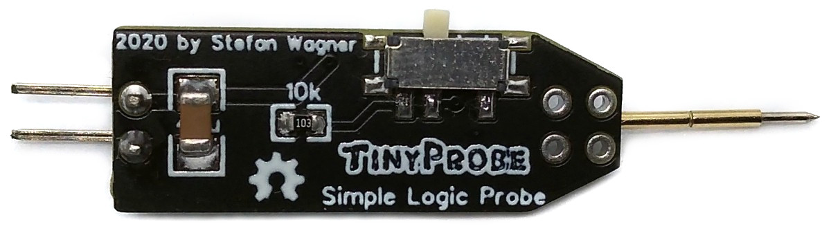
- Design Files (EasyEDA): https://easyeda.com/wagiminator/attiny13-tinyprobe
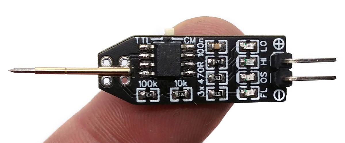
The basic wiring is shown below:
GND must be connected to ground of the test board, VCC to 5 Volts. In order to keep the device as simple as possible, input protection has been dispensed with.
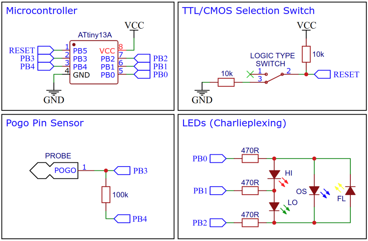
After setting up the GPIO pins, the ADC and the pin change interrupt, the tests are carried out in the main loop.
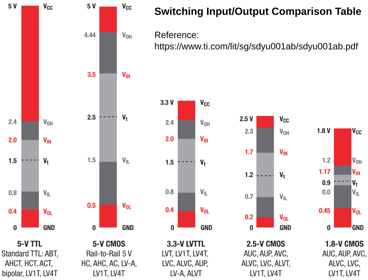
First the position of the TTL / CMOS switch is queried. Although this switch is connected to the RESET pin of the ATtiny, it does not trigger a RESET, as the voltage on the pin never drops below 40% VCC due to the voltage divider. Depending on the switch position, the voltage is VCC or VCC / 2. The threshold values for the detection of a HIGH or LOW signal are set accordingly.
// define logic levels for TTL and CMOS at 5V
#define TTL_LOW   164     // ADC value for 0.8V
#define TTL_HIGH  409     // ADC value for 2.0V
#define CMOS_LOW  307     // ADC value for 1.5V
#define CMOS_HIGH 716     // ADC value for 3.5V

// check logic level selection switch and set high/low thresholds accordingly
valLow  = TTL_LOW;                // set low value for TTL
valHigh = TTL_HIGH;               // set high value for TTL
ADMUX   = 0b00000000;             // set ADC0 against VCC
ADCSRA |= 0b01000000;             // start ADC conversion
while(ADCSRA & 0b01000000);       // wait for ADC conversion complete
valSwitch = ADC;                  // get ADC value
if (valSwitch < 768) {            // if switch is on CMOS:
  valLow  = CMOS_LOW;             // set low value for CMOS
  valHigh = CMOS_HIGH;            // set high value for CMOS
}Two methods are used to determine if the signal on the PROBE is oscillating. First of all, the pin change interrupt is activated on the PROBE pin for 1 ms in order to detect high-frequency oscillation. To do this, the 100k resistor is activated as a pull-up (PB4 as output HIGH) so that a possible floating is not accidentally recognized as an oscillation. If there is an oscillation of at least 500Hz, the interrupt is triggered at least once in this millisecond, which sets the isOscillating flag. The isOscillating flag also contains a timer value (OSC_DUR), which is decreased with each loop pass, so that even brief oscillations are visible on the corresponding LED.
// check high frequency oscillation using pin change interrupt on probe line
DDRB  |= 0b00010000;              // set pull pin to output (PB4)
PORTB |= 0b00010000;              // pull up probe line (to avoid floating)
_delay_us(10);                    // wait a bit
GIFR  |= 0b00100000;              // clear any outstanding pin change interrupt
PCMSK  = 0b00001000;              // turn on interrupt on probe pin
_delay_ms(1);                     // wait a millisecond (check >500Hz oscillation)
PCMSK  = 0b00000000;              // turn off interrupt on probe pin
// pin change interrupt service routine
ISR(PCINT0_vect) {
isOscillating = OSC_DUR; // oscillating signal on pin change
}In order to detect low-frequency oscillation, the isHigh / isLow flags are compared with the previous measurement. A change is evaluated as an oscillation, unless there is floating at the same time.
// check low frequency oscillation
if (!isFloating && ((isHigh && lastLow) || (isLow && lastHigh))) isOscillating = OSC_DUR;
lastHigh = isHigh; lastLow = isLow;In order to recognize whether a FLOATING signal is present, the input is measured once with an activated 100k pullup (PB4 HIGH) and once with an activated 100k pulldown resistor (PB4 LOW). If the two measurements differ, the isFLOATING flag is set. For the subsequent measurement with the ADC, the 100k is deactivated by setting PB4 to INPUT.
// check if probe is floating by testing the behavior when pulling up/down
isFloating = PINB;                // get input values (line is already pulled up)
PORTB &= 0b11101111;              // pull down probe line
_delay_us(10);                    // wait a bit
isFloating &= (~PINB);            // get inverse of input values
isFloating &= 0b00001000;         // mask the probe line (PB3)
DDRB  &= 0b11101111;              // set pull pin to input (disable pull)
_delay_us(10); // wait a bitIn order to recognize whether there is a HIGH or LOW signal at the PROBE, the applied voltage is measured with the analog to digital converter (ADC) and compared with the threshold values selected based on the switch position. The isLow and isHigh flags are set accordingly.
// read voltage on probe line and check if it's logic high or low
ADMUX   = 0b00000011;             // set ADC3 against VCC
ADCSRA |= 0b01000000;             // start ADC conversion
while(ADCSRA & 0b01000000);       // wait for ADC conversion complete
valProbe = ADC;                   // get ADC value
isHigh = (valProbe > valHigh);    // check if probe is logic high
isLow = (valProbe < valLow); // check if probe is logic lowLast but not least, the indication LEDs are set using a simplified Charlieplexing algorithm. If the isOscillating flag is set, the integrated timer is also decremented.
// set the LEDs (charlieplexing)
PORTB &= 0b11111000;                  // switch off all LEDs
if (isFloating) PORTB |= 0b00000100;  // if probe is floating: set FL LED
else {                                // if not floating:
  if (isLow)  PORTB |= 0b00000010;    // if probe is low:      set LO LED
  if (isHigh) PORTB |= 0b00000101;    // if probe is High:     set HI LED
  if (isOscillating) {                // if probe is oscillating:
    PORTB &= 0b11111011;              // set OS LED without interfering
    PORTB |= 0b00000001;              // with HI/LO LED
    isOscillating--;                  // decrease OS LED timer
  }
}Since there is no ICSP header on the board, you have to program the ATtiny either before soldering using an SOP adapter, or after soldering using an EEPROM clip. The AVR Programmer Adapter can help with this.
- Make sure you have installed MicroCore.
- Go to Tools -> Board -> MicroCore and select ATtiny13.
- Go to Tools and choose the following board options:
- Clock: 1.2 MHz internal osc.
- BOD: BOD 2.7V
- Timing: Micros disabled
- Connect your programmer to your PC and to the ATtiny.
- Go to Tools -> Programmer and select your ISP programmer (e.g. USBasp).
- Go to Tools -> Burn Bootloader to burn the fuses.
- Open TinyProbe.ino and click Upload.
- Make sure you have installed avrdude.
- Connect your programmer to your PC and to the ATtiny.
- Open a terminal.
- Navigate to the folder with the hex-file.
- Execute the following command (if necessary replace "usbasp" with the programmer you use):
avrdude -c usbasp -p t13 -U lfuse:w:0x2a:m -U hfuse:w:0xfb:m -U flash:w:tinyprobe.hex
- Make sure you have installed avr-gcc toolchain and avrdude.
- Connect your programmer to your PC and to the ATtiny.
- Open a terminal.
- Navigate to the folder with the makefile and sketch.
- Run
PROGRMR=usbasp make installto compile, burn the fuses and upload the firmware (change PROGRMR accordingly).

This work is licensed under Creative Commons Attribution-ShareAlike 3.0 Unported License. (http://creativecommons.org/licenses/by-sa/3.0/)