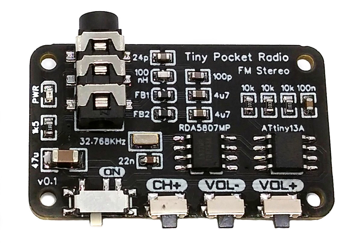
TinyPocketRadio is a simple FM stereo radio based on ATtiny13A and RDA5807MP. It's powered by a CR2032 coin cell battery and can drive 32 Ohm headphones via the 3.5 mm audio plug. The board size is 38 x 23 mm. It has a power switch and three buttons: "Channel+", Volume-" and "Volume+ ".
- Design Files (EasyEDA): https://easyeda.com/wagiminator/attiny13-tinyradio
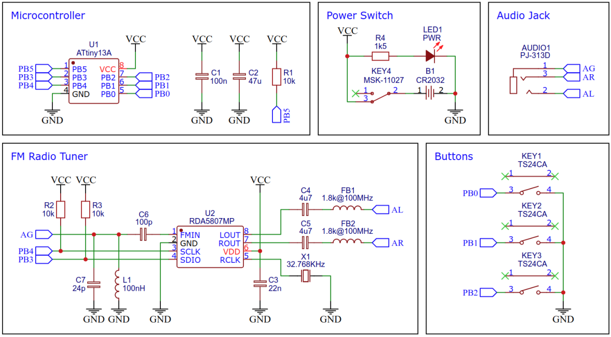
The schematic is shown below:
The low-cost RDA5807MP is a single-chip broadcast FM stereo radio tuner with fully integrated synthesizer, IF selectivity, RDS/RBDS and MPX decoder. The tuner uses the CMOS process, support multi-interface and require the least external component. All these make it very suitable for portable devices.
The I²C protocol implementation is based on a crude bitbanging method. It was specifically designed for the limited resources of ATtiny10 and ATtiny13, but should work with some other AVRs as well. Due to the low clock frequency of the CPU, it does not require any delays for correct timing. In order to save resources, only the basic functionalities which are needed for this application are implemented. For a detailed information on the working principle of the I²C implementation visit TinyOLEDdemo.
The FM tuner IC RDA5807MP is controlled via I²C by the ATtiny. It has six writable 16-bit registers (addresses 0x02 - 0x07) and six readable 16-bit registers (addresses 0x0A - 0x0F). Since no data has to be read from the device for this application, only the writable registers are used. The RDA5807 has two methods of write access, a sequential one in which the registers are always written starting from address 0x02 and an indexed method in which the register address is transferred first and then the content. Both methods are determined by different I²C addresses. To transfer the 16-bit register content, the high byte is sent first. The RDA5807 is controlled by setting or clearing certain bits in the respective registers. The details of the meanings of the individual registers can be found in the data sheet. The current register contents are saved in the RDA_regs array.
// RDA definitions
#define RDA_ADDR_SEQ    0x20              // RDA I2C write address for sequential access
#define RDA_ADDR_INDEX  0x22              // RDA I2C write address for indexed access
#define R2_SEEK_ENABLE  0x0100            // RDA seek enable bit
#define R2_SOFT_RESET   0x0002            // RDA soft reset bit
#define R5_VOLUME       0x000F            // RDA volume mask
#define RDA_VOL         5                 // start volume

// global variables
uint16_t RDA_regs[6] = {
  0b1101001000000101,                     // RDA register 0x02
  0b0001010111000000,                     // RDA register 0x03
  0b0000101000000000,                     // RDA register 0x04
  0b1000100010000000,                     // RDA register 0x05
  0b0000000000000000,                     // RDA register 0x06
  0b0000000000000000                      // RDA register 0x07
};

// writes specified register to RDA
void RDA_writeReg(uint8_t reg) {
  I2C_start(RDA_ADDR_INDEX);              // start I2C for index write to RDA
  I2C_write(0x02 + reg);                  // set the register to write
  I2C_write(RDA_regs[reg] >> 8);          // send high byte
  I2C_write(RDA_regs[reg] & 0xFF);        // send low byte
  I2C_stop();                             // stop I2C
}

// writes all registers to RDA
void RDA_writeAllRegs(void) {
  I2C_start(RDA_ADDR_SEQ);                // start I2C for sequential write to RDA
  for (uint8_t i=0; i<6; i++) {           // write to 6 registers
    I2C_write(RDA_regs[i] >> 8);          // send high byte
    I2C_write(RDA_regs[i] & 0xFF);        // send low byte
  }
  I2C_stop();                             // stop I2C
}

// initialize RDA tuner
void RDA_init(void) {
  I2C_init();                             // init I2C
  RDA_regs[0] |= R2_SOFT_RESET;           // set soft reset
  RDA_regs[3] |= RDA_VOL;                 // set start volume
  RDA_writeAllRegs();                     // write all registers
  RDA_regs[0] &= 0xFFFD;                  // clear soft reset
  RDA_writeReg(0);                        // write to register 0x02
}

// set volume
void RDA_setVolume(uint8_t vol) {
  RDA_regs[3] &= 0xFFF0;                  // clear volume bits
  RDA_regs[3] |= vol;                     // set volume
  RDA_writeReg(3);                        // write to register 0x05
}

// seek next channel
void RDA_seekUp(void) {
  RDA_regs[0] |= R2_SEEK_ENABLE;          // set seek enable bit
  RDA_writeReg(0);                        // write to register 0x02
}The code utilizes the sleep mode power down function to save power. The CPU wakes up on every button press by pin change interrupt, transmits the appropriate command via I²C to the RDA5807 and falls asleep again.
// button pin definitions
#define BT_SEEK         PB0
#define BT_VOLM         PB1
#define BT_VOLP         PB2
#define BT_MASK         (1<<BT_SEEK)|(1<<BT_VOLM)|(1<<BT_VOLP)

int main(void) {
  // setup pins
  PORTB |= (BT_MASK);                     // pull-ups for button pins

  // setup pin change interrupt
  GIMSK = (1<<PCIE);                      // turn on pin change interrupts
  PCMSK = (BT_MASK);                      // turn on interrupt on button pins
  sei();                                  // enable global interrupts

  // disable unused peripherals and set sleep mode to save power
  ADCSRA = 0;                             // disable ADC
  ACSR   = (1<<ACD);                      // disable analog comperator
  PRR    = (1<<PRTIM0) | (1<<PRADC);      // shut down ADC and timer0
  set_sleep_mode(SLEEP_MODE_PWR_DOWN);    // set sleep mode to power down

  // setup radio
  uint8_t volume = RDA_VOL;               // set start volume
  RDA_init();                             // initialize RDA
  RDA_seekUp();                           // seek a channel

  // main loop
  while(1) {
    sleep_mode();                         // sleep until button is pressed
    _delay_ms(1);                         // debounce
    uint8_t buttons = ~PINB & (BT_MASK);  // read button pins
    switch (buttons) {                    // send corresponding command to RDA
      case (1<<BT_SEEK): RDA_seekUp(); break;
      case (1<<BT_VOLM): if (volume)      RDA_setVolume(--volume); break;
      case (1<<BT_VOLP): if (volume < 15) RDA_setVolume(++volume); break;
      default: break;
    }
  }
}

// pin change interrupt service routine
EMPTY_INTERRUPT (PCINT0_vect); // nothing to be done here, just wake up from sleepSince there is no ICSP header on the board, you have to program the ATtiny either before soldering using an SOP adapter, or after soldering using an EEPROM clip. The AVR Programmer Adapter can help with this.
- Make sure you have installed MicroCore.
- Go to Tools -> Board -> MicroCore and select ATtiny13.
- Go to Tools and choose the following board options:
- Clock: 1.2 MHz internal osc.
- BOD: BOD disabled
- Timing: Micros disabled
- Connect your programmer to your PC and to the ATtiny.
- Go to Tools -> Programmer and select your ISP programmer (e.g. USBasp).
- Go to Tools -> Burn Bootloader to burn the fuses.
- Open the TinyPocketRadio sketch and click Upload.
- Make sure you have installed avrdude.
- Connect your programmer to your PC and to the ATtiny.
- Open a terminal.
- Navigate to the folder with the hex-file.
- Execute the following command (if necessary replace "usbasp" with the programmer you use):
avrdude -c usbasp -p t13 -U lfuse:w:0x2a:m -U hfuse:w:0xff:m -U flash:w:tinypocketradio.hex
- Make sure you have installed avr-gcc toolchain and avrdude.
- Connect your programmer to your PC and to the ATtiny.
- Open a terminal.
- Navigate to the folder with the makefile and sketch.
- Run
PROGRMR=usbasp make installto compile, burn the fuses and upload the firmware (change PROGRMR accordingly).
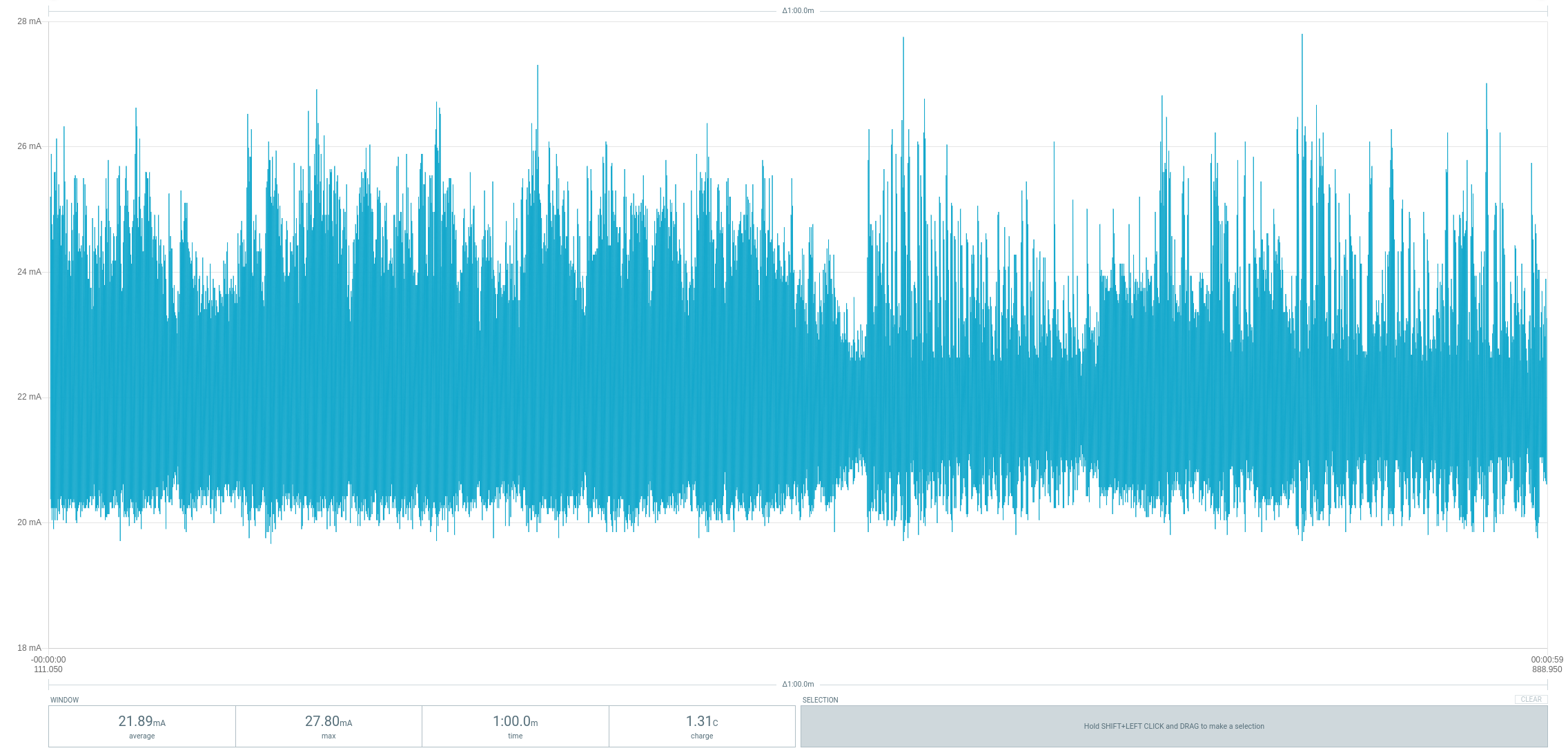
TinyPocketRadio consumes an average current of 22mA at 3V and medium volume. The typical capacity of a CR2032 battery is 230mAh. This results in a theoretical battery life of 10 hours.

This work is licensed under Creative Commons Attribution-ShareAlike 3.0 Unported License. (http://creativecommons.org/licenses/by-sa/3.0/)