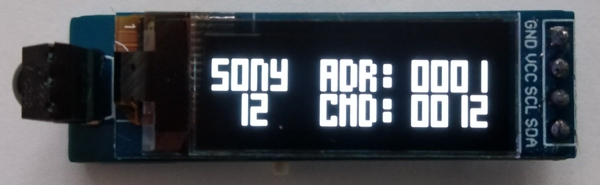
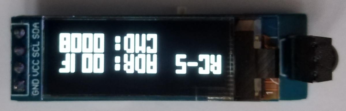
TinyDecoderIR is a simple stand-alone IR remote control receiver and protocol decoder with an OLED display based on ATtiny13A (NEC protocol only) or ATtiny25 (NEC, RC-5, SONY SIRC, SAMSUNG protocols).
- Project Video (YouTube): https://youtu.be/LEl5Z9QBuHo
- Design Files (EasyEDA): https://easyeda.com/wagiminator/attiny13-tinydetectorir
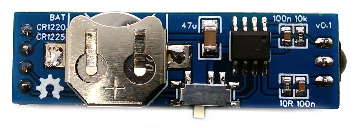
The basic wiring is shown below:
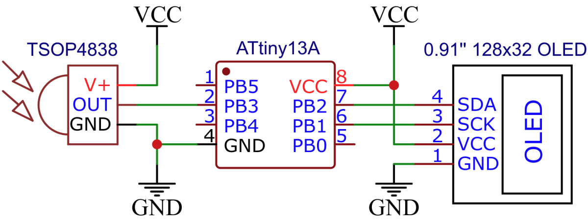
The device is powered by a 1220 coin cell battery. Please remember that only the rechargeable LIR1220 Li-Ion batteries work. The "normal" CR1220s don't deliver enough power.
The IR NEC decoding function utilizes timer0 to measure the burst and pause lengths of the signal. The timer is automatically started and stopped or reset by the IR receiver via a pin change interrupt. The measured lengths are interpreted according to the NEC protocol and the transmitted code is calculated accordingly. The program was tested with the TSOP4838, but it should also work with other 38kHz IR receivers (note different pinout if necessary).
The output of the IR reciever is inverted (active LOW), a burst is indicated by a LOW signal, a pause by a HIGH signal. IR message starts with a 9ms leading burst followed by a 4.5ms pause. Afterwards 4 data bytes are transmitted, least significant bit first. A "0" bit is a 562.5µs burst followed by a 562.5µs pause, a "1" bit is a 562.5µs burst followed by a 1687.5µs pause. A final 562.5µs burst signifies the end of the transmission. According to the data sheet of the TSOP4838, the length of the output signal differs from the transmitted signal by up to 158 microseconds, which the code must take into account. The four data bytes are in order:
- the 8-bit address for the receiving device,
- the 8-bit logical inverse of the address,
- the 8-bit command and
- the 8-bit logical inverse of the command.
The Extended NEC protocol uses 16-bit addresses. Instead of sending an 8-bit address and its logically inverse, first the low byte and then the high byte of the address is transmitted.
For a more detailed explanation on the NEC protocol refer to TinyRemote.
// pin definitions
#define IR_OUT          PB3               // IR receiver pin

// IR receiver definitions and macros
#define IR_WAIT_LOW()   while( PINB & (1<<IR_OUT))  // wait for IR line going LOW
#define IR_WAIT_HIGH()  while(~PINB & (1<<IR_OUT))  // wait for IR line going HIGH
#define IR_9000us       169                         // 9000us * 1.2 MHz / 64
#define IR_4500us       84                          // 4500us * 1.2 MHz / 64
#define IR_1687us       32                          // 1687us * 1.2 MHz / 64
#define IR_562us        11                          //  562us * 1.2 MHz / 64
#define IR_FAIL         0
#define IR_NEC          1

// global variables
volatile uint8_t IR_duration;             // for storing duration of last burst/pause
uint16_t addr;                            // for storing command code
uint8_t cmd;                              // for storing command code

// IR check if current signal length matches the desired duration
uint8_t IR_checkDur(uint8_t dur) {
  uint8_t error = dur >> 3; if (error < 6) error = 6;
  if (IR_duration > dur) return ((IR_duration - dur) < error);
  return ((dur - IR_duration) < error);
}

// IR initialize the receiver
void IR_init(void) {
  DDRB  &= ~(1<<IR_OUT);                  // IR pin as input
  PCMSK |= (1<<IR_OUT);                   // enable interrupt on IR pin
  TCCR0A = 0;                             // timer/counter normal mode
  TCCR0B = (1<<CS01) | (1<<CS00);         // start the timer, prescaler 64
  sei();                                  // enable global interrupts
}

// IR read data according to NEC protocol
uint8_t IR_readNEC(void) {
  uint32_t data;
  IR_WAIT_LOW();                          // wait for end of start pause
  if (!IR_checkDur(IR_4500us)) return 0;  // exit if no start condition
  for (uint8_t i=32; i; i--) {            // receive 32 bits
    data >>= 1;                           // LSB first
    IR_WAIT_HIGH();                       // wait for end of burst
    if (!IR_checkDur(IR_562us)) return 0; // exit if burst has incorrect length
    IR_WAIT_LOW();                        // wait for end of pause
    if (IR_checkDur(IR_1687us)) data |= 0x80000000; // bit "0" or "1" depends on pause duration
    else if (!IR_checkDur(IR_562us)) return 0;      // exit if it's neither "0" nor "1"
  }
  IR_WAIT_HIGH();                         // wait for end of final burst
  if (!IR_checkDur(IR_562us)) return 0;   // exit if burst has incorrect length
  uint8_t addr1 = data;                   // get first  address byte
  uint8_t addr2 = data >> 8;              // get second address byte
  uint8_t cmd1  = data >> 16;             // get first  command byte
  uint8_t cmd2  = data >> 24;             // get second command byte
  if ((cmd1 + cmd2) < 255) return 0;      // if second command byte is not the inverse of the first
  cmd = cmd1;                             // get the command
  if ((addr1 + addr2) == 255) addr = addr1;   // check if it's extended NEC-protocol ...
  else addr = data;                       // ... and get the correct address
  return IR_NEC;                          // return NEC success
}

// wait for and read valid IR command (repeat code will be ignored)
uint8_t IR_read(void) {
  uint8_t protocol = IR_FAIL;             // variables for received protocol
  GIMSK |= (1<<PCIE);                     // enable pin change interrupts
  do {                                    // loop ...
    IR_WAIT_HIGH();                       // wait for start conditions
    IR_WAIT_LOW();                        // wait for first burst
    IR_WAIT_HIGH();                       // wait for end of first burst
    if (IR_checkDur(IR_9000us))           // if NEC start condition
      protocol = IR_readNEC();            //   read NEC
  } while(!protocol);                     // ... until valid code received
  GIMSK &= ~(1<<PCIE);                    // disable pin change interrupts
  return protocol;
}

// pin change interrupt service routine
ISR (PCINT0_vect) {
  IR_duration = TCNT0;                    // save timer value
  TCNT0 = 0;                              // reset timer0
}The I²C protocol implementation is based on a crude bitbanging method. It was specifically designed for the limited resources of ATtiny10 and ATtiny13, but should work with some other AVRs as well. The functions for the OLED are adapted to the SSD1306 128x32 OLED module, but they can easily be modified to be used for other modules. In order to save resources, only the basic functionalities which are needed for this application are implemented. For a detailed information on the working principle of the I²C OLED implementation visit TinyOLEDdemo.
The main function just brings it all together:
// main function
int main(void) {
// setup
IR_init(); // initialize IR receiver
OLED_init(); // initialize the OLED
OLED_clearScreen(); // clear screen
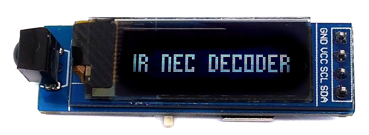
OLED_setCursor(0,1); // set cursor to start of second line
OLED_printString(IRR); // print "IR NEC DECODER"
// loop
while(1) { // loop until forever
IR_read(); // wait for and read IR signal
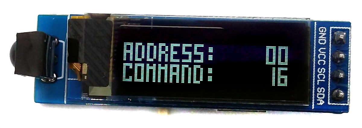
OLED_setCursor(0,0); // set cursor to start of first line
OLED_printString(ADR); // print "ADDRESS: "
if (addr > 255) OLED_printHex(addr >> 8); // extended NEC
else OLED_printString(SPC);
OLED_printHex(addr); // print received address
OLED_setCursor(0,2); // set cursor to start of third line
OLED_printString(CMD); // print "COMMAND: "
OLED_printHex(cmd); // print received command
}
}
Since there is no ICSP header on the board, you have to program the ATtiny either before soldering using an SOP adapter, or after soldering using an EEPROM clip. The AVR Programmer Adapter can help with this.
- Make sure you have installed MicroCore.
- Go to Tools -> Board -> MicroCore and select ATtiny13.
- Go to Tools and choose the following board options:
- Clock: 1.2 MHz internal osc.
- BOD: BOD disabled
- Timing: Micros disabled
- Connect your programmer to your PC and to the ATtiny.
- Go to Tools -> Programmer and select your ISP programmer (e.g. USBasp).
- Go to Tools -> Burn Bootloader to burn the fuses.
- Open TinyDecoder_t13.ino and click Upload.
- Make sure you have installed avrdude.
- Connect your programmer to your PC and to the ATtiny.
- Open a terminal.
- Navigate to the folder with the hex-file.
- Execute the following command (if necessary replace "usbasp" with the programmer you use):
avrdude -c usbasp -p t13 -U lfuse:w:0x2a:m -U hfuse:w:0xff:m -U flash:w:tinydecoder_t13.hex
- Make sure you have installed avr-gcc toolchain and avrdude.
- Connect your programmer to your PC and to the ATtiny.
- Open a terminal.
- Navigate to the folder with the makefile and sketch.
- Run
PROGRMR=usbasp make installto compile, burn the fuses and upload the firmware (change PROGRMR accordingly).
The 1 KB flash of the ATtiny13 is too small to implement the decoding of several protocols in combination with an OLED display (at least I didn't manage to do it). Fortunately, there are pin-compatible models with more memory. The ATtiny25 is available in the same package (150mil SOIC-8, e.g. ATtiny25-20SSU) and double flash memory. In order not to reinvent the wheel, I took David Johnson-Davies' excellent implementation of his IR Remote Control Detective for the ATtiny85 and adapted it so that it works with the 2 KB flash of the ATtiny25. In addition to the NEC protocol, Samsung, Sony and RC-5 can also be decoded without further hardware adjustments.