
(You can find the documentation in German at https://www.mikrocontroller.net/articles/STECCY.)
- Emulation of all Z80 instructions - even the undocumented ones.
- Timing is similar to that of a Z80 CPU at 3.5MHz.
- Support of displays with SSD1963 or ILI9341 controllers
- Enlarged display of the ZX-Spectrum display incl. "border" on TFT with 800x480 pixels
- Different ZX-Spectrum ROMs possible
- Loading and saving of TAPE data via SD card
- Simulation of the Spectrum keyboard by a PS/2 or USB keyboard
- Support of an original ZX-Spectrum keyboard (matrix)
- Joystick emulation with Wii Nunchuk or Wii Gamepad or via PC keyboard
- Patching games by POK files (infinite lives etc.)
- Control of the two board LEDs via Z80-OUT commands (BASIC or assembler)
- Control of STM32-USART2 via ZX-Basic PRINT and INPUT commands
STECCY emulates a ZX Spectrum 128K or Spectrum 48K on a STM32F407VET black board, which can be purchased for about 10 euros on eBay or Aliexpress. In addition, STECCY can be compiled under QT, so that STECCY can also be used under Windows and Linux. There is also a framebuffer and X11 port to Linux, so that STECCY also runs on a Raspberry PI in the console or on the desktop.
As an emulator, STECCY not only reproduces the instruction set of a Z80 CPU, but also parts of the ZX Spectrum hardware. The 256x192 Spectrum display is shown on a TFT display with a magnification of 2:1 - i.e. with a resolution of 512x384 pixels.
Some examples:
| ZX Basic | Manic Miner | Jetset Willy |
|---|---|---|
 |
 |
 |
Loading and saving programs is done via an SD card, which is FAT-formatted. Here, the cassette recorder routines in the virtual ROM are converted to load and save routines for SD cards. STECCY supports TAP, TZX and snapshot files for this purpose. Snapshots can be used to freeze and save the current state of the emulated ZX spectrum at any time. This makes it possible, for example, to continue playing a game the next day at exactly the same time as it was saved as a snapshot.
The ZX-Spectrum 128K or ZX-Spectrum 48K is emulated. The virtual Spectrum 128K has a ROM with a size of 32KB and RAM with a size of 128KB, the Spectrum 48K has a ROM with a size of 16KB and RAM with a size of 48KB.
Not only the documented, but also all undocumented instructions of a Z80 CPU are reproduced. This is especially important for games, as some ZX Spectrum games use undocumented instructions.
At http://clrhome.org/table/ you can find all possible Z80 instructions. The documented ones have a grey background, the undocumented ones have a red background and make up the vast majority of all Z80 instructions.
The following ZX Spectrum hardware is emulated by STECCY:
- Z80 through timing-accurate emulation of a 3.5MHz clocked Z80 CPU
- ULA chip for display and interrupts
- ZX keyboard through PS/2, USB keyboard or ZX keyboard matrix
- Cassette recorder through SD card
- Spectrum ROMs through file on SD card
In the original, the Spectrum ULA is responsible for the playback of the Spectrum screen. It reads the required 6912 bytes from the RAM of the spectrum at a rate of 50Hz. This is done analogously by STECCY: Here, the TFT display is also updated 50 times per second. However, an optimisation takes place here: Only the changed data is retransmitted to the TFT in order to save time.
The ULA chip also takes care of the Z80 interrupt, which ensures that the keyboard routines in the RAM are jumped to in order to read out the matrix keyboard of the Spectrum. Various system variables are also updated, such as a 16-bit uptime counter. Depending on the current interrupt mode (IM0/IM1/IM2), STECCY uses the resulting addresses as interrupt jump addresses and then calls the corresponding interrupt routine. This jump address is in ROM by default, but many games change it to their own addresses in RAM, for example, to update the spectrum screen without flickering.
The Sinclair operating system, namely the ZX-Spectrum 128K or 48K ROM, consists of 16KB or 32KB data, which are mostly Z80 instructions. Since the copyright holder Amstrad has released the contents to the public domain, as long as the copyright notice remains intact, it is no problem to use the original ROM of the ZX-Spectrum 128K or even 48K for such an emulation. Yes, you are even allowed to redistribute the contents.
See also Amstrad ROM permissions
You will find original ROM files from Sinclair in the folder "rom":
- 128.rom - Original Sinclair ROM 128K
- 48.rom - Original Sinclair ROM 48K
- 48u.rom - Like 48.rom, but with additional stream #4 for input/output via STM32-UART2.
For 48u.rom see also STM32 hardware extensions below.
Modifications and new implementations of the ZX-Spectrum-ROMs are also available. The original ROM as well as many modifications and extensions can be found at Philip Kendall - The Spectrum ROMs collection.
If you simply don't want to get used to the exotic command input of basic tokens by single keys, the "GOSH WONDERFUL ZX Spectrum ROM" for the ZX-Spectrum 48K is recommended. Here the BASIC commands are entered via single keys. The Spectrum 128K already provides the input of the basic tokens via single keys in the 128K-Basic anyway.
The GOSH-ROM can be downloaded here as file gw03.rom: The GOSH WONDERFUL ROM
This URL also lists all improvements, bug fixes and extensions compared to the original Sinclair ROM.
The ZX Spectrum manual is also freely available: World of Spectrum Documentation ZX Spectrum manual.
If you don't want to translate the complete source code, you can also flash the HEX files directly:
- steccy-ili9341.hex for STM32F407VET6 with ILI9341 TFT display
- steccy.hex for STM32F407VET6 with SSD1963 TFT display
For installation, it is sufficient to flash the right HEX file on the STM32F407VET6, see above
If you want to compile the program yourself, you can use the IDE EmBitz, see also www.embitz.org.
In EmBitz, 4 target variants are configured:
- ILI9341-Debug
- ILI9341-Release
- SSD1963 debug
- SSD1963-Release
SSD1963-Release should then be selected for the SSD1963 display. If you use the ILI9341 display, select ILI9341-Release.
As an alternative to EmBitz, you have to create a corresponding project or Makefile yourself. For this, the following options for the compiler should be set in addition to the optimisation (-O2 or -Os) and various warning levels:
 -DARM_MATH_CM4
 -D__FPU_USED
 -DSTM32F407VE
 -DSTM32F4XX
 -DUSE_STDPERIPH_DRIVER
 -DHSE_VALUE=8000000
 -fno-strict-aliasing
 -DSSD1963
If you want to create the program version for ILI9341 displays, replace the option -DSSD1963 with -DILI9341.
The QT source is in the subdirectory steccy-qt, the Linux source in the subdirectory steccy-lx. For instructions see STECCY under Linux below.
To start STECCY, at least the ROM files, namely 128.rom and 48.rom, should be available on the SD card. The SD card is formatted as FAT32 on the PC, 128.rom and 48.rom are copied onto it and then inserted into the SD card slot of the STM32F407VET black board. In addition, you can also place the above-mentioned gw03.rom on the SD card and then load the GOSH ROM via the STECCY menu.
Furthermore, other ZX Spectrum programs can be stored on the SD card, namely as TAP, TZX or Z80 files. The latter are snapshots of the emulated ZX-Spectrum 128K or ZX-Spectrum 48K.
The structure of these files is explained here, among other things:
- TAP: ZX Spectrum tape file: format specification
- TZX: TZX FORMAT
- Snapshots: Z80 File Format
The TZX file format is much more flexible than the TAP format. TZX also allows compression and fast loading routines that used to exist for the ZX Spectrum. However, STECCY only supports loading via the standard ROM routines (compressed and uncompressed), so fast loaders are not supported. Over 95 per cent of ZX-Spectrum programs use the ROM routines, so there are no problems there.
If you find a program/game in both formats (TAP and TZX), <ou should prefer the TAP file. If the program is in TZX format, it can happen in rare cases that STECCY cannot load this file completely. However, the probability is less than 5 per cent. In this case, you can also use the ZX Spectrum emulator "Fuse", which is freely available for Windows and Linux, to import the quick loader file there and then save it again as a snapshot. The snapshots can then also be used for STECCY without any problems.
The software for using the SD card is FatFs - Generic FAT Filesystem Module. Many thanks to ChaN for this!
Please note: The STM32 displays the file names in format 8.3, which means you should not use more than 8 characters before the dot.
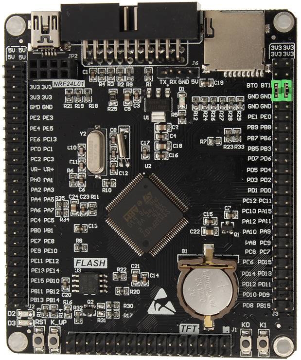
The following components, among others, are installed on the BlackBoard:
- STM32F407VET6
- FSMC connector for TFT
- SD card slot
- USB connection
- 8 MHz and 32 kHz quartz
- SPI Flash W25Q16
- 2 freely usable LEDs
- 3 user buttons
- Socket for RTC battery
- Socket for NRF24L01
Complete circuit diagram of the STM32F407VET6-BlackBoard: STM32_F4VE_SCHEMATIC.PDF
Complete overview of pin assignments: STM32F407VET6 black board
Individual overview of pin assignments:
- JTAG and TFT: Black STM32f4VET6-2 Pinouts JTAG-TFT.pdf
- Pinouts left side: Black STM32f4VET6-2 Pinouts Left.pdf
- Pinouts right side: Black STM32f4VET6-2 Pinouts Right.pdf
- Pinouts left and right side: Black STM32f4VET6-2 Pinouts Left-Right.pdf

The 3.2 inch display with ILI9341 controller and RGB interface can be used as the smallest display. This is simply plugged onto the TFT connector of the STM32F407VET6 BlackBoard without any further soldering.
The display is available for 11 EUR at Aliexpress.
However, the 3.2 inch display is quite small. 5" or 7" displays are more fun, see below. For STECCY, the FSMC connector for the display and the SD card slot are needed. Furthermore, a few pins are used for keyboard and other purposes.


A 7 inch TFT display with 800x480 pixels and SSD1963 controller can be used as the display. A touch screen is optional, but not required. You will find this display at eBay or Aliexpress for approx. 30-35 EUR by using the keywords "SSD1963 7" inch TFT LCD Module Display 800x480". The touch field is not supported by STECCY, but is otherwise not a problem. If you find the same display without touch screen at a lower price, you should simply use this one.
This display is also available in the same resolution as a 5 inch display for less than 30 EUR. This can also be used. The SSD1963 controller and the resolution of 800x480 pixels are important.
The display is connected to the TFT pin socket of the STM32F407VET BlackBoard via the parallel FSMC interface of the STM32 as follows:
| STM32 TFT Pin | FSMC Name | STM32 Pin | Display Pin | Display Name | Remarks |
|---|---|---|---|---|---|
| 1 | GND | GND | 1 | GND | TFT GND |
| 2 | RST | RST | 33 | REST | SSD 1963 RESET |
| 3 | FSMC D15 | PD10 | 27 | DB15 | FSMC DB15 |
| 4 | FSMC D14 | PD9 | 25 | DB14 | FSMC DB14 |
| 5 | FSMC D13 | PD8 | 23 | DB13 | FSMC DB13 |
| 6 | FSMC D12 | PE15 | 21 | DB12 | FSMC DB12 |
| 7 | FSMC D11 | PE14 | 19 | DB11 | FSMC DB11 |
| 8 | FSMC D10 | PE13 | 17 | DB10 | FSMC DB10 |
| 9 | FSMC D9 | PE12 | 15 | DB9 | FSMC DB9 |
| 10 | FSMC D8 | PE11 | 13 | DB8 | FSMC DB8 |
| 11 | FSMC D7 | PE10 | 16 | DB7 | FSMC DB7 |
| 12 | FSMC D6 | PE9 | 14 | DB6 | FSMC DB6 |
| 13 | FSMC D5 | PE8 | 12 | DB5 | FSMC DB5 |
| 14 | FSMC D4 | PE7 | 10 | DB4 | FSMC DB4 |
| 15 | FSMC D3 | PD1 | 8 | DB3 | FSMC DB3 |
| 16 | FSMC D2 | PD0 | 6 | DB2 | FSMC DB2 |
| 17 | FSMC D1 | PD15 | 4 | DB1 | FSMC DB1 |
| 18 | FSMC D0 | PD14 | 2 | DB0 | FSMC DB0 |
| 19 | FSMC NOE | PD4 | 11 | RD | FSMC /RD |
| 20 | FSMC NWE | PD5 | 9 | WR | FSMC /WR |
| 21 | FSMC A18 | PD13 | 7 | RS | FSMC /RS |
| 22 | FSMC NE1 | PD7 | 29 | CS | FSMC /CS |
| 23 | T_SCK | PB13 | 18 | T_CLK | Touch (n.u.) |
| 24 | T_CS | PB12 | 20 | T_CS | Touch (n.u.) |
| 25 | T_MOSI | PB15 | 22 | T_DIN | Touch (n.u.) |
| 26 | T_MISO | PB14 | 26 | T_DO | Touch (n.u.) |
| 27 | T_PEN | PC5 | 28 | T_IRQ | Touch (n.u.) |
| 28 | LCD BL | PB1 | -- | -- | n.c. |
| 29 | n.c. | -- | -- | -- | n.c. |
| 30 | GND | GND | 1 | GND | TFT GND |
| 31 | 3V3 | 3V3 | 3 | 3V3 | SSD1963 |
| 32 | GND | GND | 1 | GND | TFT GND |
| -- | 5V | 5V | 35 | 5V | s. Text |
Since the backlight of the display draws approx. 400mA as current, the 5V supply of the display should not be done via the STM32 board, but directly via a 5V power supply unit with at least 1, better 2 amps. This can then also supply the STM32 board. There are enough pins for 5V on the STM32 board. It is therefore not necessary to use the USB plug for the power supply. Under no circumstances should the BlackBoard be operated via the 5V pin socket and the USB plug at the same time!
To power the backlight, do the following:
- DO NOT connect LED_A - pin 37
- Connect 5V (pin next to it) directly to the 5V power supply unit
- Close the solder bridge "Always On" on the display board
The pin assignments of the STM32407VET6-BlackBoard can be seen here: STM32F407VET6 black board Complete schematic of the STM32F407VET6 black board: STM32_F4VE_SCHEMATIC.PDF
The pin assignment of the display can be found here: Schematic.pdf
The designations are also printed directly next to the pin socket on the display board itself.
With the F1 key, you can choose between 4 orientations during operation:
| Mode | Orientation |
|---|---|
| 0 | Flip None (Standard) |
| 1 | Flip Vertical |
| 2 | Flip Horizontal |
| 3 | Flip Vertical + Horizontal |
You can save the orientation in the INI file "steccy.ini". To do this, you count how often you had to press the F1 key to see the picture the right way round.
This value is entered in the INI file as
ORIENTATION=0 # or 1, 2, 3
Likewise, there are TFT displays whose RGB colour sequence is wired differently. If the display shows wrong colours, you can change the RGB colour sequence with the F2 key.
This can also be saved in the INI file "steccy.ini".
Enter here:
RGB=0 # Standard order RGB
RGB=1 # Non-standard is GRB
STECCY supports an original ZX Spectrum keyboard (Matrix) as well as a PS/2 or USB keyboard for character input. It is even possible to use all three keyboard variants at the same time, which can be useful for games for 2 players. The keys that are also available on the ZX Spectrum are mapped 1:1 in the PC keyboard conversion. Other keys on the PC keyboard are mapped to combinations of Spectrum keys.
For this purpose, STECCY converts Z80-IN commands that address the spectrum matrix keyboard to the corresponding mapped keys, which are read from the keyboard at regular intervals.
The following applies to the PC keyboards:
- The TAB key changes to the STECCY menu.
- F1 sets the orientation of the TFT display
- F2 switches the display between the colour sequence RGB and GRB
- F3 switches the turbo mode (unbraked emulation) on and off again
- F12 terminates STECCY (applies only to the Linux version)
- The left Shift key corresponds to the CapsShift key on the ZX Spectrum.
- The right Shift key corresponds to the Shift key on the PC keyboard used.
- Both the left and right CTRL keys correspond to the Symbol Shift key on the ZX Spectrum.
- The ESC key corresponds to the CapsShift-Space key combination, i.e. it generates "BREAK".
- The four arrow keys generate the combinations CapsShift-5 to CapsShift-8, i.e. they correspond to the ZX-Spectrum cursor keys.
- The keys of the right number field are used for joystick emulation, see "Joystick emulation".
- Y and Z are swapped on German keyboards, because the English layout is kept as far as possible.
Examples:
- Pressing "j" generates the command "LOAD" in Basic command mode.
- The plus key "+" on the PC keyboard generates the key combination "SymbolShift-K", i.e. "+".
- The plus key "+" together with the right shift key on the PC keyboard generates the key combination "SymbolShift-B", i.e. "*".
- Left Shift key together with "5" produces "Cursor-Left".
- Right Shift key together with "5" produces "%".
- Left arrow key creates "CapsShift-5", i.e. "Cursor-Left".
As mentioned above, an attempt is made to retain the English keyboard layout as far as possible. On the German PC keyboard, Y and Z therefore appear reversed. This is intentional, because some games use exactly these keys. If the emulation were to swap these two keys again so that they come closer to the German layout, one would have to perform seemingly impossible "monkey grips" in order to still be able to operate the game.
For orientation: Images of ZX Spectrum keyboards can easily be found via Google by entering "zx spectrum keyboard layout".
Good example: Sinclair ZX Spectrum keyboard layout
 PS/2 Female connector from the front
The PS/2 keyboard is connected via a 4-wire cable as follows:
| PS/2 | STM32 | Remarks |
|---|---|---|
| CLOCK | PB7 | pulled up to 5V via 4.7K |
| DATA | PB6 | pulled up to 5V via 4.7K |
| GND | GND | |
| 5V | 5V |
Don't forget to add the two pullup resistors!
The USB keyboard is connected to the Mini USB port of the STM32F407 blackboard via a Mini USB to USB-A adapter.
Important:
Since in this case the STM32 acts as USB host (in HID mode), the pull-up resistor R21 (1.5K) on the STM32F407VET6 blackboard marked "V2.0" must be desoldered. Otherwise the USB keyboard will not be recognised.

In the meantime, there are also black boards with the identification "V33" on the back. The resistor circled in the photo no longer exists. There is still a resistor R21 at another location, but it has a different function. In this case, therefore, no intervention is necessary.
The desoldering is not tragic at all, since the external resistor is superfluous in the STM32F4XX family, even in operation as a USB device (and not USB host). In the case of operation as a USB device (and not as a host), the internal pull-up of the STM32F4XX intended for this purpose is automatically used.
If the USB keyboard is recognised when STECCY is started, the LED D2 (usually red, sometimes green) lights up on the blackboard.
STECCY also supports external ZX-Spectrum matrix keyboard. Here the matrix must be connected as follows:
** ZX Spectrum Keyboard Matrix**
| Row | STM | ADDR | D0 | D1 | D2 | D3 | D4 | D4 | D3 | D2 | D1 | D0 | ADDR | STM | Row | |
|---|---|---|---|---|---|---|---|---|---|---|---|---|---|---|---|---|
| 3 | PC3 | A11 | 1 | 2 | 3 | 4 | 5 | 6 | 7 | 8 | 9 | 0 | A12 | PC4 | 4 | |
| 2 | PC2 | A10 | Q | W | E | R | T | Y | U | I | O | P | A13 | PC5 | 5 | |
| 1 | PC1 | A9 | A | S | D | F | G | H | J | K | L | CR | A14 | PC6 | 6 | |
| 0 | PC0 | A8 | CS | Z | X | C | V | B | N | M | SS | SP | A15 | PC7 | 7 | |
| STM | PE0 | PE1 | PE2 | PE3 | PE4 | PE4 | PE3 | PE2 | PE1 | PE0 | STM |
Summarised:
PC0 - PC7: Row 0 - 7
PE0 - PE4: column 0 - 4
If someone still has an original ZX keyboard, the following assignment of the connection foil will help:
              Columns                           Lines
              --- --- --- --- ---               --- --- --- --- --- --- --- ---
Z80           D0  D1  D2  D3  D4                A11 A10 A9 A12 A13  A8  A14 A15
STM32F407     PE0 PE1 PE2 PE3 PE4               PC3 PC2 PC1 PC4 PC5 PC0 PC6 PC7
Note that the conductive areas on the foils are applied differently - once at the top (columns) and once at the bottom (rows).
Furthermore, an additional column 5 (at PE5) is provided to which up to 8 additional keys for special functions can be connected. So far, only one additional key is supported, namely the one that connects PC0 to PE5. This is used to access the STECCY menu. The use of the remaining special function keys is planned.
The following applies to the ZX keyboard
- The key on PE5/PC0 is used to enter the STECCY menu.
The following keys function in the STECCY menu:
- CS 6 - Arrow down: Next menu item
- CS 7 - Arrow up: Previous menu item
- CS 0 - DELETE: Delete backwards
- A - Z - A - Z: Letters
- 0 - 9 - 0 - 9: Numbers
- SS J - SymShift J: Minus
- ENTER - ENTER: Confirm menu item
- CS SPACE - BREAK: Exit menu item

The variant of connecting the ZX Spectrum keyboard as a matrix via 13 cables has a serious disadvantage: the display together with the blackboard cannot be mounted far away from the ZX keyboard.
For this reason, there is an alternative: The ZX Spectrum keyboard is converted to a PS/2 keyboard. Then it can be connected to the BlackBoard via a longer thin PS/2 cable.
Here the rows/columns are connected to the STM32F103 on a BluePill board as follows:
              Columns                           Lines
              --- --- --- --- ---               --- --- --- --- --- --- --- ---
Z80           D0  D1  D2  D3  D4                A11 A10 A9  A12 A13 A8  A14 A15
STM32F103     PB3 PB4 PB5 PB6 PB7               PA3 PA2 PA1 PA4 PA5 PA0 PA6 PA7
Pin PB8 serves as an additional column for extensions. Again, an additional button can be placed between PB8 and PA3 to start the STECCY menu.
| PS/2 | STM32F103 | Remarks |
|---|---|---|
| CLOCK | PB12 | pulled up on STM32F407 |
| DATA | PB13 | pulled up on STM32F407 |
| GND | GND | |
| 5V | 5V |
For more informations see the separate project on Github: STECCY-Keyboard
STECCY can simulate digital joysticks using the right-hand numeric keypad on the PC keyboard.
The following joysticks are supported:
- Sinclair Joystick 1
- Sinclair Joystick 2
- Kempston Joystick
- Cursor Joystick
Keyboard layout:
| Key | Function |
|---|---|
| 0 | Fire |
| 1 | Down Left |
| 2 | Down |
| 3 | Down Right |
| 4 | Left |
| 5 | Down (as 2!) |
| 6 | Right |
| 7 | Up Left |
| 8 | Up |
| 9 | Up Right |
In addition to the "2" key, the "5" key also acts as a "joystick down". Reason: The four main directions are thus closer together and enable faster play in jump-and-run games.
You can also use a Wii Gamepad or Wii Nunchuk controller as a joystick. These are available as clones for a few euros on eBay.


The two Wii devices use the I2C protocol. For the connection with the STM32 4 connections are necessary, namely:
- SCL
- SDA
- 3.3V
- GND
It is best to cut the connector and connect the cable ends directly to the pins on the STM32 board. The colours of the cables are listed here:
| Pin Nunchuk | Color Original | Color Clone | Pin STM32 |
|---|---|---|---|
| 1 | green | yellow | PB9 (SDA) |
| 2 | n.c. | black | n.c. |
| 3 | red | green | 3.3V |
| 4 | white | red | GND |
| 5 | n.c. | n.c. | n.c. |
| 6 | yellow | white | PB8 (SCL) |
Since you have usually purchased a clone, you cannot rely on the colours. It is better to unscrew the connector and see the cable colours for yourself. My clone had the colour sequence given above. As an alternative to the cut-off method, there are also adapters for the Nunchuk plugs available on eBay. These can also be used for the Wii Classic Gamepad.
The Nunchuk controller has 2 buttons, namely the upper "C" button and the lower "Z" button. The latter serves as the fire button, the "C" button as the menu button with which you can both enter and exit the STECCY menu. The analogue stick is shown as a digital joystick - namely in the respective emulation.
| Key | ZX Spectrum | STECCY Menu |
|---|---|---|
| "Z" below | Fire | Select menu entry or change selection |
| "C" above | Start Menu | Back |
| Stick up | Joystick up | Menu entry up |
| Stick down | Joystick down | Menu entry down |
| Stick left | Joystick left | Page up |
| Stick right | Joystick right | Page down |

The gamepad controller has the same connections as the nunchuk controller, see above.
Only the button assignments are different because the gamepad controller has many more buttons to operate.
| Key | ZX Spectrum | STECCY Menu |
|---|---|---|
| Select | Turbo Mode | -- |
| HOME | Start Menu | Back |
| Start | Z80 Reset | -- |
| Any other button | Fire | Select menu entry or change selection |
| Stick up | Joystick up | Menu entry up |
| Stick down | Joystick down | Menu entry down |
| Stick left | Joystick left | Page up |
| Stick right | Joystick right | Page down |

An active loudspeaker or a small audio amplifier can be connected to PC13 of the STM32. Active PC speakers, for example, work immediately.
If you want to integrate something smaller into a STECCY enclosure, you can also set up an adjacent amplifier and connect a small speaker, e.g. one with 0.25W and 27mm diameter. R9 and R10 are in fact a potentiometer with 5k for volume adjustment.
A cleaner solution would be to use 2 additional diodes to compensate for the BE-threshold voltage and reduce distortion. However, in view of the inferior sound quality, which the original Spectrum already had, these diodes can be dispensed with.
Many of the ZX Spectrum games are now public domain. Information about copyrights can be found here: ARCHIVE - COPYRIGHTS AND DISTRIBUTION PERMISSIONS. If in doubt: If you own the original game in the form of a compact cassette, you are on the safe side.
In general, World of Spectrum and Spectrum Computing are the places to go for general information about the ZX-Spectrum or to download programmes/games. The archive provides access to text adventures, utilities and over 10,000 games for the ZX-Spectrum. Please pay attention to copyrights!
The following popular games, among many others, have been successfully tested under STECCY and run flawlessly:
- Manic Miner
- Jet Set Willy II
- Bubble Bobble (use TAP!)
- Chuckie Egg
- Pac-Man
- Jetpac
- Space Rider
- Hocace goes Skiing
- Lode Runner
- Booty
- The Hobbit
The links refer to the game description in the archive. There, under "Files", you will find the TZX and TAP files.
If you are looking for a specific game on World of Spectrum, it is best to use the search in the "Infoseek" submenu. The hits again refer to the archive. Searching the archive itself is much more tedious given the amount of data.
Many games do not offer any help at all for operation - especially with regard to the keys to be used.
In many jump-and-run games, the buttons are often:
- o to the left
- p to the right
- q upwards
- a down
- Space bar: fire or other action
For Manic-Miner and Jet Set Willy it is
- o to the left
- p to the right
- Space bar: jump
In other games (such as Bubble Bobble), you can also select the key assignment or set it yourself. Or there is help at the beginning. If none of this helps, you have to try it out.
If the games offer joystick operation, you should select a joystick type that can also be set in STECCY.
Then you can play the game with the number pad keys as a joystick simulator. 0 is fire, the keys 1-9 are clear. Many games also work clandestinely with the Kempston or cursor joystick. You should simply change this in the menu and try out whether the keys react.
Especially on the STM32, it can happen with the game "Bubble Bobble" that the bubbles are not displayed correctly on the screen in the 48K emulation. In this case, "Bubble Bobble" should be started in the 128K emulation. The problem does not occur here.
The STECCY menu can be activated with the TAB key on the PC keyboard. The menu can be exited again with the ESC key.
Keys to use:
| Key | Wii | Function |
|---|---|---|
| Tab | "C" above | Enter menu |
| Down | Stick down | Next item |
| Up | Stick up | Previous item |
| Right or Page Down | Stick right | Page down |
| Left or Page Up | Stick up | Page up |
| ENTER or Space | Fire ("Z" below) | Select item or change selection |
| ESC or BREAK (Shift Space) | "C" above | Leave menu |
The following menu items are available:
Here you can select a joystick to be simulated via the numeric keypad.
Possibilities:
- Sinclair Joystick 1
- Sinclair Joystick 2
- Kempston Joystick
- Cursor Joystick
You can switch between these alternatives with the space key ("SPACE") to select the correct joystick type.
In the QT version, the menu item "Joystick" does not exist. Here you can simply switch between the joystick simulations with the TAB key. The current simulation is shown below the spectrum display.
This menu item only exists in the QT version. A mouse click pauses the emulator. Another click continues the emulation.
In the STM32 version, you can freeze the emulation with the PAUSE key. Another press on PAUSE continues the emulation.
RESET emulates a hardware reset of the ZX-Spectrum. After a short time the copyright message of the Sinclair ROM should appear.
Here you can select the ROM to be used at start-up. All files on the SD card with the file extension ".ROM" are displayed for this purpose.
The name of the standard ROM file is "128.rom". Would you like to emulate the original ZX Spectrum 48K, you can load here "48.rom". An alternative to the 48K ROM would be "gw03.rom", see above.
Recommendation:
RAM=128.rom
Here you can set whether a BASIC programme should be started directly after a LOAD command so that it can reload further data. This is the standard case with the ZX-Spectrum, if the Basic programme has been saved accordingly. Therefore, the standard setting here is "YES".
In the ST version this setting is changed with the space bar, in the QT version with a mouse click on the tick.
This menu item is omitted from version 1.5.2. Instead, the file selection menu for TAPE files is now loaded automatically when you instruct the ZX Spectrum to load a file from tape - either by the ZX Spectrum TAPE LOADER or via the LOAD "" instruction.
The table of contents of the files on the SD card is then displayed. Here you can now load the TAPE file into the virtual cassette recorder by selecting it. TAP, TZX or Z80 files can be selected. In the case of snapshots (ending .Z80), the file is loaded immediately and the ZX Spectrum is set to the state saved in the snapshot.
For TAP and TZX files, an additional action is necessary:
he key combination for loading a programme for the ZX Spectrum 48K is
LOAD "" (keys: j CTRL-P CTRL-P RETURN)
If the AUTOSTART setting is YES, the program ist started automatically.
If there is also a POK file of the same name for the loaded TZX or TAP file, this menu item is automatically activated. In this case, you can select entries from this POK file in order to become immortal for certain games, jump to new levels, etc.
A vast number of POK files for all conceivable games can be found at https://github.com/ladyeklipse/all-tipshop-pokes.
Here you can either overwrite an existing TAPE file or create a new file on the SD card. After entering the file name, leave the menu and enter in the BASIC interpreter:
SAVE "Example" (keys: s CTRL-P Example CTRL-P RETURN).
The Spectrum then displays the familiar message Start tape, then press any key. After confirming the message with RETURN, the program is saved to the TAPE file under the name "Example" in TZX format.
If the program is to be started automatically after loading from a certain line (e.g. line 10), use the command:
SAVE "Example" LINE 10 (keys: I leave to the inclined reader ;-) ).
You can now save further data in the previously selected tape file, which will then be appended, e.g. a code area from the RAM. The command for this is, for example:
SAVE name CODE 32768,8192 (keys s name CapsShift-SymbolShift i)
If you want to close the tape file, select "Stop Record" in the STECCY menu. The "recording" is then stopped.
The current state of the ZX spectrum is saved here. After entering the file name, RAM content and all Z80 registers are stored in the selected snapshot file. This can be loaded again later, for example to continue playing a game that has been started.
The following keys can be used in the main menu or in the submenus:
Pre-settings can be made in the INI file steccy.ini. For the QT version, the INI file must be located where steccy.exe is also located. For the STM32 version, the file must simply be copied to the SD card.
Linux and QT version: This defines the search path where the ROM file and the TAPE files can be found. The default is the current directory if neither PATH is specified or the entry after the equal sign is empty.
STM32: The entry is ignored
Example for QT under Windows:
PATH=c:\steccy
Example for Raspberry PI console or X11 desktop:
PATH=/home/pi/steccy
The name of the ROM file to be loaded automatically at startup. The default is "128.rom".
Example: ROM=48.rom
Specifies whether Basic programmes saved with Autostart should actually be started automatically. Default is "yes". Alternative is "no". The recommended setting is "yes".
Example: AUTOSTART=yes
Name of the TAPE file that is automatically loaded into the virtual tape player. Default is none.
Example: AUTOLOAD=manic.tzx
Specification of the keyboard used.
Possible values:
KEYBOARD=PS2
KEYBOARD=USB
KEYBOARD=ZX
Here are:
PS2: PS/2 PC keyboard
USB: USB PC keyboard
ZX: ZX Spectrum Matrix keyboard
Several keyboards can be specified by repeating the KEYBOARD line, e.g.
KEYBOARD=PS2
KEYBOARD=ZX
In this case, you can use a PS/2 and a ZX matrix keyboard at the same time. This can be useful for multi-user games.
If no value is given for KEYBOARD, this is identical to the setting:
KEYBOARD=PS2
This means: If not specified, the PS/2 keyboard are is active.
Orientation on the TFT display. Default is 0. Only for STM32. In the QT version this entry is ignored.
The possible values are:
| Mode | Orientation |
|---|---|
| 0 | Flip None (default) |
| 1 | Flip Vertical |
| 2 | Flip Horizontal |
| 3 | Flip Vertical + Horizontal |
Example:
ORIENTATION=1
The F1 key can also be used to change the orientation during operation. At the end of the chapter Display, it is explained how to find out the correct value for your display.
RGB colour sequence on the TFT display. Most TFTs work with the RGB colour sequence, some with the GRB sequence. The default setting is therefore RGB=0.
The following applies:
RGB=0        # Standard order is RGB
RGB=1        # Non-standard is GRB
This value should only be changed if false colours appear on the TFT.
The basic command BORDER 2 should create a red screen border. If the border appears in a different colour, you should change the value. This can easily be tested with the F2 key. This switches between the two values.
Comments can be introduced in the INI file with "#" or ";".
Example for a complete INI file:
# PATH: Default is current directory (only QT and Linux), e.g. PATH=/home/pi/steccy
PATH=c:\steccy
# ROM: Default is 128.rom
ROM=128.rom
# Autostart: Default is yes
AUTOSTART=yes
# Autoload: Default is none
AUTOLOAD=
# Keyboard: Default is PS2 and USB. Use ZX for ZX-Spectrum matrix keyboard
KEYBOARD=PS2
# Orientation: Default is 0 (only STM32)
ORIENTATION=1
# RGB Order: Default is 0 (only STM32)
RGB=0
STECCY also runs on the Linux desktop (X11) or frame buffer of a Linux console, for example on a Raspberry PI.

Log in as a normal user, e.g. as user "pi". Enter the following commands in the console:
 cd
 mkdir src
 cd src
 wget https://github.com/ukw100/STECCY/archive/refs/heads/main.zip -O steccy.zip
 unzip steccy.zip
 cd steccy/steccy-lx
 cp steccy.ini $HOME/.steccy.ini
Ensure development environment is installed:
sudo apt-get install build-essential
Then build and install program 'steccy':
make steccy
sudo make steccy-install
Turbo mode can be switched on with the F3 key or via the ZX Spectrum software.
In this mode, the ZX Spectrum runs unbraked, i.e. under full CPU load. Furthermore, there is the possibility to switch on special "ROM HOOKS". In this case, special ROM routines are implemented by native CPU instructions of the STM32 or PC. At present, the BASIC commands "PLOT" and "DRAW" are accelerated when the ROM HOOKS are switched on.
The OUT address for activating the ROM hooks is 65151.
The following OUT commands can be used to switch the individual TURBO modes:
| Value | Function |
|---|---|
| 254 | Turbo Mode on |
| 253 | ROM Hooks on |
| 252 | Turbo Mode and ROM Hooks on |
| 0 | All Optimizations on |
| 255 | All Optimizations off |
== Assembler ==
If you want to play around with Z80 assembler, the online assembler https://www.asm80.com/onepage/asmz80.html is recommended.
Here you can have Z80 assembler source texts translated directly and download the compilation as a TAP file. You can then load the compilation directly into STECCY and try it out.
Example: CHAN_OPEN equ 5633 ; open channel routine in ROM PRINT equ 8252 ; print routine in ROM
         org  32768                     ; program start at 32768
         ld   a, 2                      ; stream number
         call CHAN_OPEN                 ; open channel
         ld   de, text                  ; pointer to text
         ld   bc, textend-text          ; length of text
         jp   PRINT                     ; jump to PRINT in ROM
text defb 'Hello, this is STECCY!' ; output string defb 13 ; carriage return textend equ $
This programme outputs "Hello, this is STECCY!" on the ZX Spectrum screen.
Procedure:
- Call https://www.asm80.com/onepage/asmz80.html
- Copy assember code into text area
- Press button "ASSEMBLE and make .TAP"
- Download compilation and save it, e.g. as "hello.tap"
- Input on STECCY: CLEAR 32000 LOAD "" CODE RANDOMIZE USR 32768
Select hello.tap when querying the TAPE file.
The desired message should then appear on the display. However, if you want to output the message via the UART2 of the STM32, change the line ld a, 2 into ld a, 4
to use stream #4. However, the ROM 48u.rom is necessary for this, see above.
The programme corresponds to the BASIC command PRINT "Hello, this is STECCY!" respectively PRINT #4;"Hello, this is STECCY!"
Make sure libx11-dev is installed:
sudo apt-get install libx11-dev
Then create and install the programme 'xsteccy':
make xsteccy
sudo make xsteccy-install
Install STECCY desktop icon (LXDE desktop on Raspberry PI):
cp steccy.desktop $HOME/Desktop
cp steccy.desktop $HOME/.local/share/applications/
Afterwards, the STECCY ICON should appear on the desktop as well as in the start menu under "Games".
This completes the installation. If necessary, the file $HOME/.steccy.ini should be adjusted with the editor. The search path where the ROM and TAPE files are located is entered there.
PATH=/home/pi/steccy
We now create this directory in the home directory:
cd
mkdir steccy
and then download the ROM files and put them in this directory. Tape files for games etc. should also be stored exclusively in this directory.
If you want to use a different directory for the ROM and TAPE files, you have to adapt the file $HOME/.steccy.ini with the editor.
STECCY for Linux runs not only on the desktop, but also in a framebuffer console. If you have installed a desktop and still want to start STECCY as a console programme, you must first switch to the text console with CTRL-F1 (Console #1) or CTRL-F2 (Console #2).
To start, one then enters
steccy
With the F12 key, STECCY can be terminated again. Press F7 to return to the desktop. But this only works if STECCY has been closed before!
Normally, the current console resolution is retained. If you want to run STECCY in full screen, enter:
steccy -g 800x480
for a 16:9 monitor. On a 4:3 monitor use:
steccy -g 800x600
You can also play around with other resolutions. However, you should not go below a width of 800.
The easiest way to start STECCY is via the STECCY desktop icon or via Start-Menu -> Games -> STECCY.
However, it can also be started from the command line. Here you enter:
xsteccy &
In this case xsteccy opens a window with the size 800x480. You can also choose other window sizes with the option '-g'. In this case, however, only the window is enlarged, not the emulated ZX Spectrum screen.
STECCY is also terminated here with the F12 key.
Have fun with STECCY!