is a repo for a very cheap Arduino-controller PCB flow / reflow oven for the after-population soldering of existing Printed circuit boards (PCBs). Contributors are github user @twinbee @ILMPBx
The approach taken is low budget / minimum viable product (MVP). The oven features one LED for status, and one button for control.
Many others have produced fancy ovens with OLED / TFT diplays and many buttons. This is not that.. This is minimal and cheap enough to get a good result; No more, no less.
Licensed under the Mozilla Public License 2.0 (MPL2). See LICENSE for more details. Copy right Matthew Bennett, Luke Andrews 2016.
- A cheap toaster oven ($24 new or $15 thrifted)
- Solid state relays capable of a few amps (two, about $9 each)
- Arduino. I used an UNO I had lying around. ($25)
- USB cable for programming or changing profile ($5)
- Type K thermocouples (one or two, $11 each)
- A way to get the thermocouple data to the arduino. We used a 1-wire board from
- Push button ($1)
Sum total is about $125
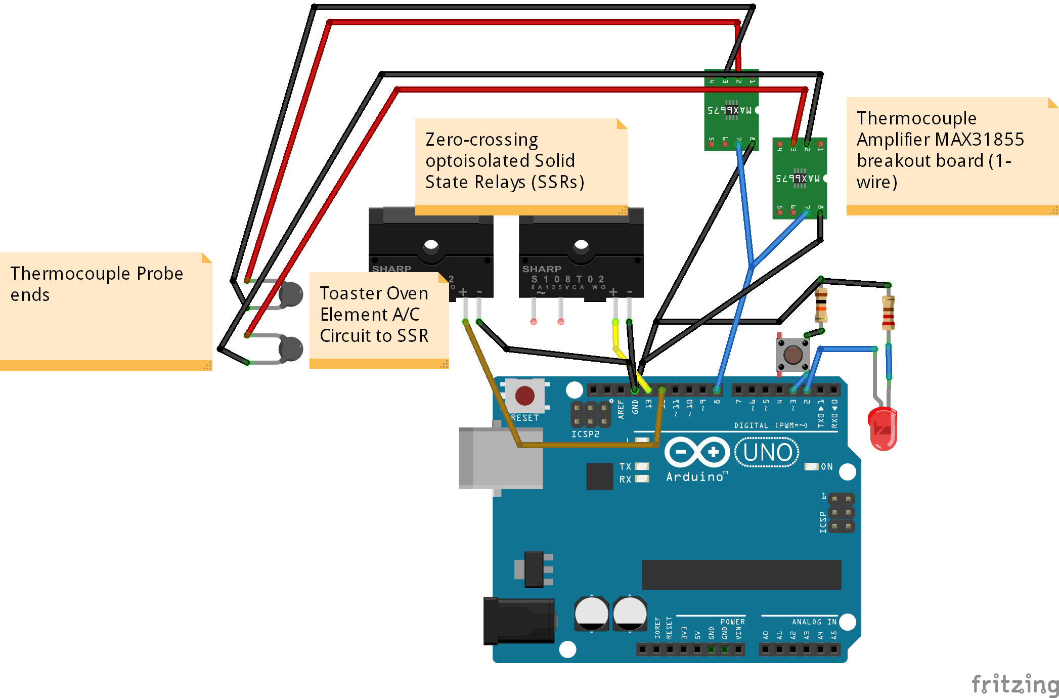
Wire the elements to the AC side of an SSR. Be sure to include the door switch and the fire prevention over-temperature sensor that came with your oven as series elements in the circuit, if applicable. Wire a pin on the arduino to the DC side of the SSR. Do not solder any connections which will live inside the toaster if you can avoid it, as the side cavity of a toaster oven may get hot enough to melt solder. Instead, crimp and use heat shrink. Use either quick disconnect terminals or butt-splice connectors.
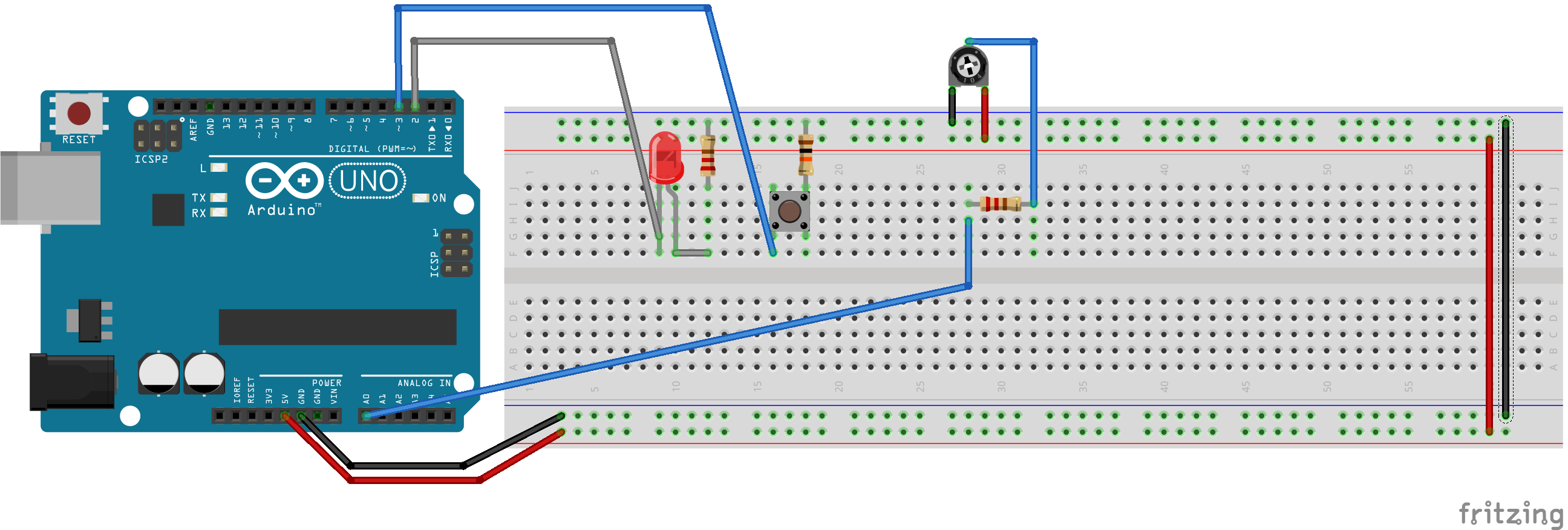
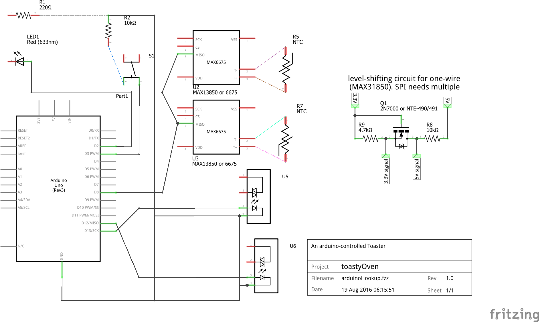
On the DC side, connect the arduino pin 13 to the SSR as illustrated in the fritzing diagram or image found in the designs folder. Connect the button to arduino pin 2 via a 10KOhm pull-down resistor. Connect the LED to arduino pin 3 via a 220-Ohm pull-down resistor (or similar value based on the LED color and desired brightness). Connect the thermocouple amplifier to arduino pin 8 via the instructions from the thermocouple amplifier manufacturer (e.g. adaFruit). Connect a USB cable to computer if serial output desired, otherwise connect a USB cable to USB port supply. Connect a piezo buzzer to Arduino pin 5 if sound is desired. Put everything together physically and move on to the profile step.
duino Contains the Arduino-based controller code. designs contains physical designs including some 3d-printable parts with sketchup models and wiring schematics. processingContains code to take serial input from the arduino and plot it as a graph of temperature over time, for further tweaking
The toaster may have a number of baking profiles up to the total number allowed by Arduino program memory space constraints. To select a profile, press the button the number of times desired until the LED is blinking the correct number for that profile. If you go past the last profile the selection will loop back to the first one.
When you are satisfied, hold the button down for three seconds without releasing it, and the profile will begin. Once the profile has completed, the toastyOven is reset and awaiting another profile / run.
Each profile should be written as a function with a function pointer stored in the global array profiles near the top of the code. Examples are provided.
void profile1()
{
//times are in seconds
//temps are in degrees Centigrade

  Serial.println("profile1: MEMS mics");
// Preheat 160C
//Dwell 120s
//Ramp Up 1C/s for 98s
//Dwell  30s
//Ramp Down 1C/s for 98s
//Ramp Off
cookTemps[0] = 160;
cookTimes[0] = 120;

cookTemps[1] = 220;
cookTimes[1] = 30;

cookTemps[2] = 160;
cookTimes[2] = 60;

cookTemps[3] = 40;
cookTimes[3] = 30;

}
After writing your profile, be sure to add it to the functor list and adjust numProfiles.
const int NUM_PROFILES = 3;
void (* profiles  [NUM_PROFILES]) () = { profile1, profile2, profile3 };
If you wish to increase the number of stages in a profile, it is here. Just be sure to zero out the profiles you aren't using.
const int NUM_STAGES = 4;
int cookTemps[NUM_STAGES] = {0,0,0,0};
int cookTimes[NUM_STAGES] = {0,0,0,0};
You may also want to configure the hysteresis buffer with a different temperature range.
// a buffer used for hysteresis / dampening.
//  within epsilon degrees is "good enough"
//  to count time toward our goal time for
//  that stage
// Use half the value that you actually want
// so if you want the range to be 10 degrees,
//  e.g. 500C +/-5C, use 5.0C
int tempEpsilon = 5;
That's it! Enjoy a tasty circuit board at home.
For our project, everything we needed was in a cabinet to the right side of the toaster. We removed all mechanical timers / knob controls and we left the emergency over-temp breaker device and the door switch in series with the power coming in.
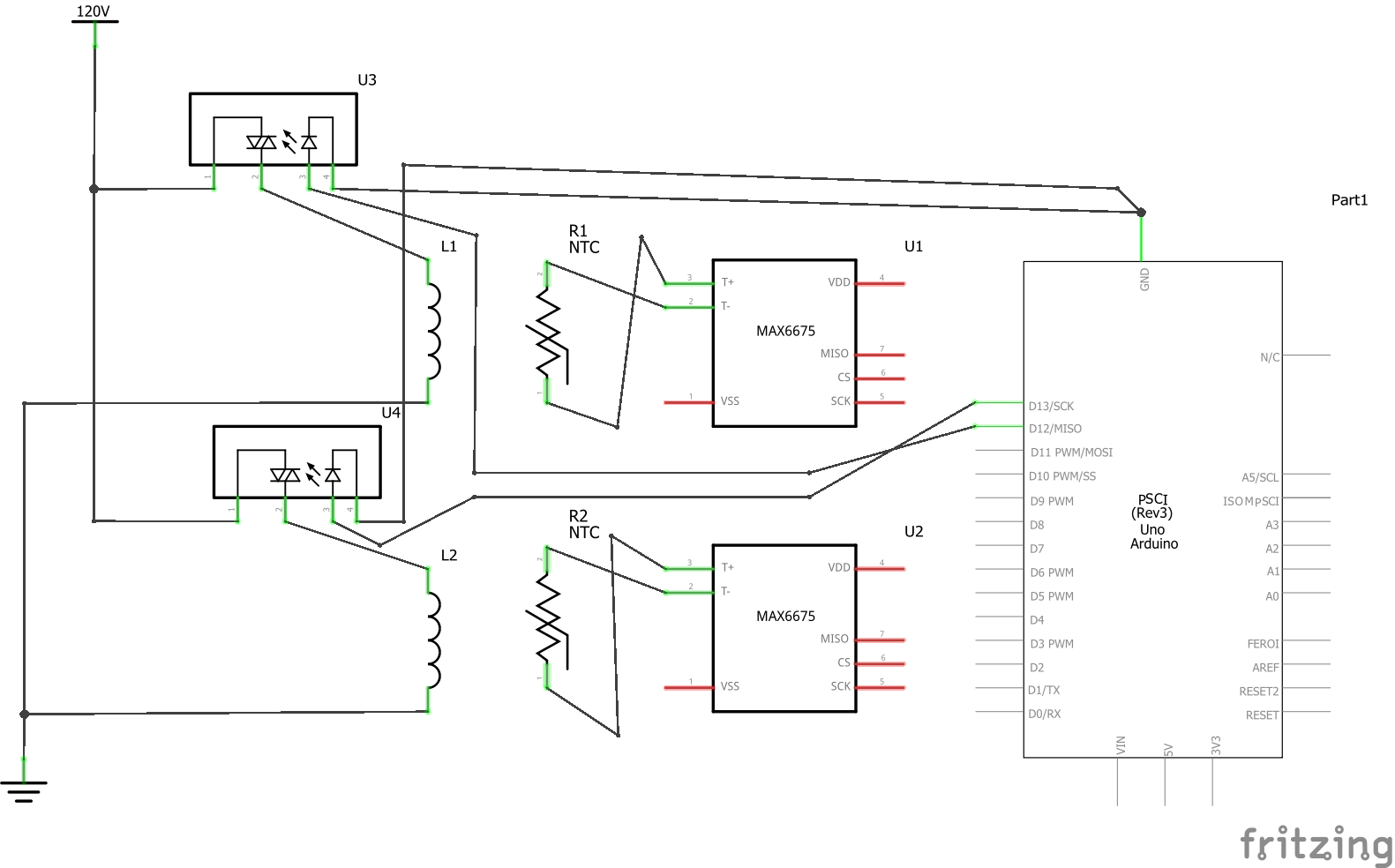
Figure: AC side wiring
If you don't have the thermocouple circuit, you can use a simple 10K-Ohm potentiometer on one of the Analog input pins. If you don't have the toaster oven element circuit / SSR, you may use an LED to show when the oven element(s) are on.