The device creates a series of tones and lights and requires a user to repeat the sequence. If the user succeeds, the series becomes progressively longer and more complex. Once the user fails, the game is over.
Each round, there is one more LED to the sequence and it goes faster. There are also 4 difficulties: very easy, easy, normal and hard. The difference between them is how much faster the sequence will be displayed. The speed of the sequence is determined by a delay between each LED.
The game starts with a delay of 500 ms and will decrease each round for a minimum of 100 ms.
- Very easy: 15 ms
- Easy: 30 ms
- Normal: 45 ms
- Hard: 60 ms
The game stop when the player fails or reaches 100 rounds.
The LCD screen display information to the user while is playing.
- 1 Arduino Uno Board rev.3
- 1 LCD screen 16x2
- 1 Piezzo buzzer
- 1 Potentiometer 10k ohm
- 4 LEDs (4 differents colors)
- 4 Pushbuttons
- 5 Resistors 220 ohm
- 4 Diodes
You can find the whole circuits in the fritzing file (fzz or pdf).

As well as saving I/O lines, this circuit automatically lights up the corresponding LED when you press a button. To read the status of a push button program the I/O line as an input, and to light a LED program the line as an output and leave it low.
The four diodes are not strictly necessary, but protect each I/O line in case the line is inadvertently programmed as an output and taken high while the push button is pressed. They can be low cost signal diodes such as the 1N4148.
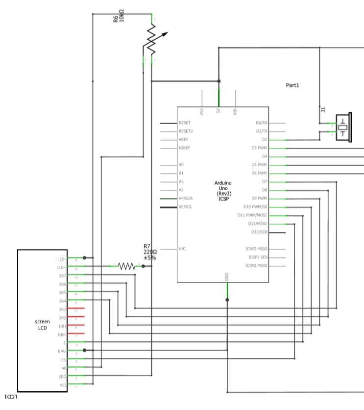
The wiring for the LCD is the basic wiring:
- LCD RS pin to digital pin 12
- LCD Enable pin to digital pin 11
- LCD DB4 pin to digital pin 10
- LCD DB5 pin to digital pin 9
- LCD DB6 pin to digital pin 8
- LCD DB7 pin to digital pin 7
- LCD VSS pin to ground
- LCD VDD pin to 5V
- LCD V0 pin to potentiometer
- LCD R/W pin to ground
- LCD LED- to ground
- LCD LED+ to resistor
A register select (RS) pin that controls where in the LCD's memory you're writing data to.
A Read/Write (R/W) pin that selects reading mode or writing mode
An Enable pin that enables writing to the registers
4 data pins (DB4 -DB7). The states of these pins (high or low) are the bits that you're writing to a register when you write, or the values you're reading when you read.
There's also a display constrast pin (Vo), power supply pins (+5V and Gnd) and LED Backlight (Bklt+ and BKlt-) pins that you can use to power the LCD, control the display contrast, and turn on and off the LED backlight, respectively.