An ESP32 TFT interpretation of the @deruiter's DCF77-Analyzer-Clock-V2.0
- ESP32
- TFT (160*128 minimum recommended, working on elastic design to cover higher resolutions)
- DCF77 Atomic clock module ( such as this one https://www.universal-solder.ca/product/canaduino-60khz-atomic-clock-receiver-module-wwvb-msf-jjy60/ (WWVB/JJY60/MSF/DCF77) or https://www.pollin.de/p/dcf-77-empfangsmodul-dcf1-810054 (DCF77))
- RTC Module (preferably i2c, e.g. a 5V DS1307 or 3V3 DS3231)
- Buttons (optional)
- Speaker (optional)
- M5Stack Core or ESP32-Chimera-Core for compatibility https://github.com/tobozo/ESP32-Chimera-Core (replaces M5Stack Core, adds support for Odroid-Go, TTGO-TS, Wrover-Kit LoLin D-32Pro)
- Bodmer's JPEGDecoder for rendering jpeg in sprites https://github.com/Bodmer/JPEGDecoder
(Contributed by dl9sec)
Thanks to the ESP32-Chimera-Core, the clock runs fine and flawless on an ODROID-GO (with sound output and buttons support for A/B/MENU).
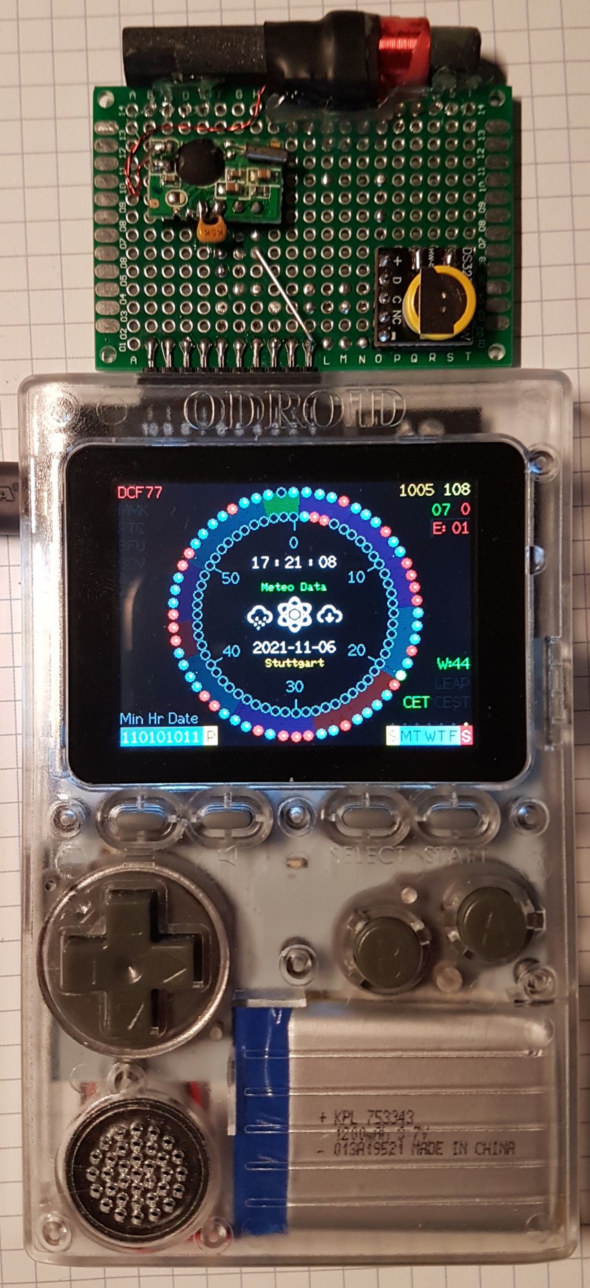
The hardware components has to be connected to the ODROID-GO's 10-pin connector:
- The DCF modules positive pulse output has to be connected to
IO4(5). - The RTC should be a DS3231 for convenience (3V3 system). Connect the supply pins to the ODROID-GO
P3V3(6) andGND(1),SDAtoIO15(4) and SCL toIO12(3) (hopefully the RTC will never need to do a clock stretching, becauseIO12is a buffered output pin, not an open-collector/-drain).
To build a suitable ODROID-GO firmware file the following steps have to be proceeded:
- Uncomment the
#define CONFIG_OGOin theConfig.h(comment out any other of the platforms). - Activate the verbose compiler output at the Arduino IDE preferences.
- Select the
ORDOID ESP32as target in the Arduiono IDE. - Build the firmware (just clicking the checkmark).
- When successfully finished the build process, watch one of the last lines of the Arduino IDE console output and navigate to the temporary directory where the compiler puts the file
esp32-DCF77_Analyzer_Clock.ino.elf. - There you will find a file named
esp32-DCF77_Analyzer_Clock.ino.bin. Copy this file to a directory (of your choice), where the executablemkfw(Linux) ormkfw.exe(Windows, get it here: https://forum.odroid.com/viewtopic.php?t=31939) could be found. - Copy the file
\assets\img\OGO_DCF77_Analyzer_Clock_Logo.rawto the same directory (icon file created as described here). - Create the firmware with
mkfw "DCF77 Anylyzer Clock" OGO_DCF77_Analyzer_Clock_Logo.raw 0 16 1048576 app esp32-DCF77_Analyzer_Clock.ino.bin(Windows) or./mkfw "DCF77 Anylyzer Clock" OGO_DCF77_Analyzer_Clock_Logo.raw 0 16 1048576 app esp32-DCF77_Analyzer_Clock.ino.bin(Linux). - Rename the file with
ren firmware.fw esp32-DCF77_Analyzer_Clock.fw(Windows) ormv firmware.fw esp32-DCF77_Analyzer_Clock.fw(Linux). - Put the firmware file
esp32-DCF77_Analyzer_Clock.fwto your ODROID-GO's SD card in theodroid\firmwarefolder and install it from there to your ODROID-GO. - After a software reboot you need to power the ODROID-GO off and on again to re-init the incomplete graphics.
I learned a lot from Erik de Ruiter who learned a lot from the work of Matthias Dalheimer and Thijs Elenbaas who made their own DCF77 decoders.
Although the changes I made are far from optimistic, this code has wisdom DNA in its roots!
Without the incredible work of these geniuses I would not have known where to start and how to write those credits :)
Huge thanks to @BrettOliver for fueling the code with a 320x240 UI, implementing the leap second, and much more
- Inspirational video : https://www.youtube.com/watch?v=ZadSU_DT-Ks
- UI code based on : https://github.com/deruiter/DCF77-Analyzer-Clock-V2.0
- Crypto code based on : https://github.com/FroggySoft/AlarmClock
- Weather code based on : http://arduino-projects4u.com/home-weather-station/
- Erik de Ruiter : https://www.hackster.io/edr1924
- Brett Oliver : http://www.brettoliver.org.uk/
- Joop Tap : http://www.jooptap.nl
- Thijs Ellenbaas : http://thijs.elenbaas.net/2012/04/arduino-dcf77-radio-clock-receiver-hardware-2/
- Mathias Dalheimer : https://github.com/roddi/DCF77-Arduino/blob/master/DCF77Servoclock/DCF77.h
- DCF77 wikipedia : https://en.wikipedia.org/wiki/DCF77
- Much more DCF77 info : http://www.picbasic.nl/indexes_uk.htm
- Erik de Ruiter's Flickr : https://www.flickr.com/photos/edr1924/albums
- Erik de Ruiter's Github : https://github.com/deruiter
- FroggySoft's Github : https://github.com/FroggySoft