There are many Stereo SID boards out there, but this one is mine - mostly because I did not feel like tracking down or paying premium to get one of those wirewrap sockets. Using a simple board like this will put a second SID chip at $DE00 and add 3 voices to your system, with suitable software and a selection of SID files you can play music on your system like never experienced before (your mileage may vary)! For everyday use you can use it in pseudo stereo-mode by having each SID play the same thing simultaniously.
As with anything dealing with SID chips you should know what you are doing, this board does not deal with the specific power requirements used between SID types and putting the wrong thing in there will certainly kill the chip you value the most or both of them! Personally I built the board with the intention of using it with substitutes like SwinSID, SwinSID Ultimate and ARMsid and all those should be perfectly safe to use in any combination (that way you don't deprive a C64 of its audio qualities).
The stock computer does not have any way of connecting up the audio from the second SID, the standard A/V cables are naturally mono as that is what the system was designed to be. This means you'll need to add relevant connectors to your system such as RCA sockets, either in the form of custom-made cables hanging out the back or by drilling and adding the connectors to your case (please don't drill into a case and expect me to buy it later). A third option is to replace the modulator with one that adds something like a 3.5mm stereo audio connector, which is what I did with my other PCB for C64-Modulator-Replacement.
Soldering together the few components should be easy going as long as you have access to reasonable tools, personally I'm using a cheap soldering station with adjustable temperature so no need to go expensive if you don't have to. Use 60/40 soldering tin, the lead free makes to job a lot harder if you're new to the hobby.
Start by studying the PCB, both sides and perform dry fits to see that you have an idea of where everything goes since removing things is always a lot harder than getting it right in the first place (match orientation to symbols, see gallery images for reference).
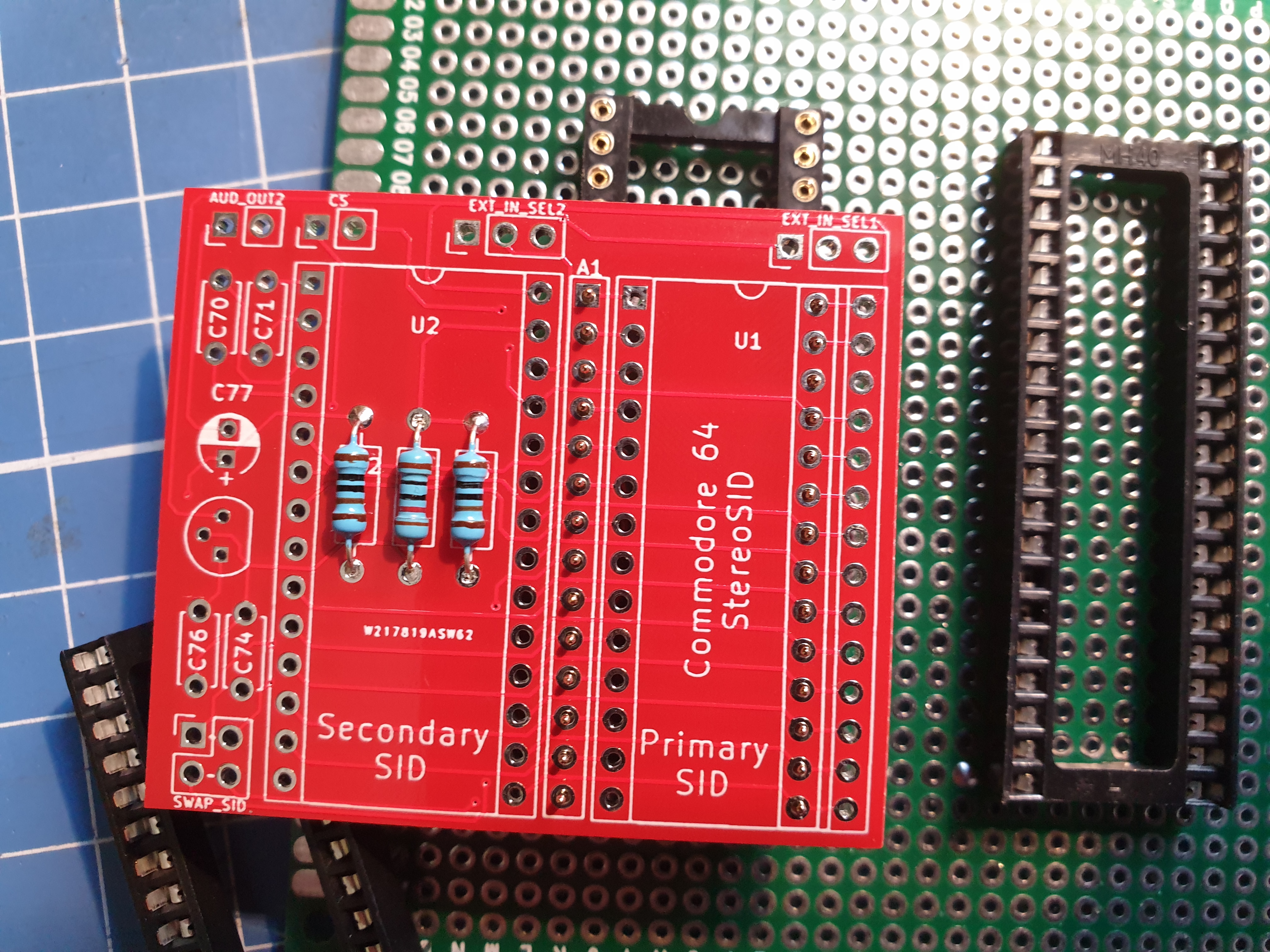
With a lot going on for such a tiny board, you'd need to pay some attention to the sequence of components getting soldered in. The list below is the one I recommend, note that with some sockets you'll have less space underneath and it'll be a lot easier getting it into place if you trim the pins after they have been soldered into place. When aligning the two 14-pin (round) pin-headers I recommend using a round-pin socket to help keep them straight, that way you won't get issues trying to install it into the Commodore 64.
- Check errata below
- Resistors, see note on dowmixing below.
- 14 pin-headers on the marked A1 as well as a similar one on the right side (solder on reverse-side). Refer to this image for reference.
- Sockets for U1/U2
- Capacitors according to values on silkscreen, note the different value for C70/C71 according to the type of SID chips that belong in the system you are installing it.
- Remaining components
The board has components for downmixing the audio coming out of both SID chips down to a mono signal, via the installation of two resistors - R2 and R3. If you want your stereo to be in, well - stereo - then the suggested route is installing a wire in place of R2 and leaving the spot for R3 blank.
- Revision B has a missing trace between the top of R1 and the bottom of D1, you can add a wire between them to restore functionality when using two chips in pseudo-stereo mode. For reference, the missing wire is the only green wire in the following picture.
The board should slot nicely into the existing socket for the previous SID, this is removed and usually installed as the primary SID on the Stereo SID board. There may be components such as capacitors that interfere with the new board, take care to examine and gently bend away those that are in the way before firmly pushing it into the socket.
Below you can see a picture of the board installed in one of the classic breadbins, without the "breadbin"-part at the moment. Here I have the 6581 installed as my primary SID chip, the rather excellent ARMsid is installed as my secondary chip and is available at $DE00 given the default installation of the CS-wire (white) going to seventh pin of the cartridge expansion port (counted from the left). The audio output of the second SID (green) has been routed to the stereo audio jack on my system though, as already discussed in the introduction, you may opt for something else entirely.

Note the 3-pin header pins, designated EXT_IN_SEL1 and EXT_IN_SEL2 - these connect up the audio coming into the system on the standard A/V cables. I usually leave these unjumpered in order to avoid mixing stray noise into the outgoing sound, but some people like to have these connected straight to ground by jumpering across pins 2-3. When using equipment expecting the SID to mix in externally generated audio such as the Currah uSpeech, jumper the primary SID to pins 1-2.
Given that most software don't know how or even where to look for a Secondary SID, you don't immediately get stereo sound on your system - the software need to have this functionality added to it. There is a great page at lyonlabs.org/commodore/stereo-sid with a wealth of information on how to get going with it, I recommend starting with StereoPlayer 10.2 as part of the section called "Playing Stereo SIDs" as that is the one I ended up using with this board (also comes with a few sample steareo SID-files).
Press the Commodore-key to change StereoPlayer configuration, press A to cycle address to $DE00 and push M to change mode to stereo. Personally I also had to turn Fast Load off before loading files as I was not using a fastloader cartridge with my Pi1541, this stopped a few of the issues I was having when listing disk contents and loading music files. Press the "<--"-key to save configuration for later, the Commodore-key returns you to the menu. Select a Stereo SID file from the list and add it to the list to play them - I had some isssues with some files that were not recognized, so I found that not using the play all button worked best for me.
Other than that, enjoy the glorious feeling of playing those Stereo SID files on the Commodore 64!


The supplied KiCad files should be sufficient as both a schematic and as a starting point for ordering PCBs (basically you could just zip the contents of the export folder and upload that on a fabrication site), the schematic is also available in PDF-format and this is what you'll need to print and work your way through this things don't work as expected after assembly.
Most parts should be easy to get a hold of from your favourite local electronic component shop, but given that I don't have access to such shops where I live so everything was based on whatever I could get cheapest from ebay/AliExpress (free shipping, plan on usually waiting 3-4 weeks though). The list below should be everything you'll need in addition to a workable soldering iron and some 60/40 soldering tin.
Pin headers you order in bulk and snap off parts as needed, but note that you should get round pin headers for the part that goes into the socket - while you can use the regular kind if needed, you may easily wear out or end up breaking the socket. Relevant part details have also been added to the PCB itself.
| Reference | Item | Count |
|---|---|---|
| PCB | Fabricate using Gerber files (order) | 1 |
| C70/C71** | 470pF (6581) or 22nF (8580) capacitor | 2 |
| C74 | 1000pF capacitor | 1 |
| C76 | 470pF capacitor | 1 |
| C77 | 10uF electrolytic capacitor | 1 |
| D1, D2 | 1N4148 small signal diode | 2 |
| J1-J3 | 3-pin straight header | 3 |
| J4 | 2-pin straight header | 1 |
| R1,R12 | 1k ohm resistor | 2 |
| R2 | Install wire for standard stereo | (1) |
| R2, R3 | 1k ohm resistor (downmix to mono) | (2) |
| R8* | 1k ohm resistor | (1) |
| R9 | 10k ohm resistor | 1 |
| Q1 | 2N2222 transistor (TO-92) | 1 |
| A1 | 14-pin round pin header | 2 |
| U1, U2 | 28-pin wide socket | 2 |
* R8 - not installed on motherboards that use 8580 SID chips
** C70/C71 - Install either both 470pF for motherboards supporting 6581, 22nF for motherboards supporting 8580.