See too: Examples and tutorials found on the Internet for using the resources of the STM8
-
Note: This repository is no longer a fork of the original.
-
- To allow new forks and issue openings in case a bug is found
-----> Do not use the board without checking the relay LED problem. See below at "W1209 hardware (variation)"
- Note: On W1219 board, the LED is controlled independently of the relay.
- Apparently there is a bug in the compiler SDCC (v. 4.0.0), in case the display malfunctions when modifying the code:
-
- Add a 'long' variable in the first file (name in alphabetical order) *.c
a_file.c:
#include "a_file.h"
long foo;
-
Updates and new features have been added (Uses less program memory than the Arduino IDE).
-
- Navigation between files and references is easier than in the Arduino IDE.
-
- (apparently all functions working)
-
Makefile compilation mode, similar to the original way.
-
- (No more editing the Makefile file manually to modify source filenames).
-
Remote version (serial port emulated by timers) here.
-
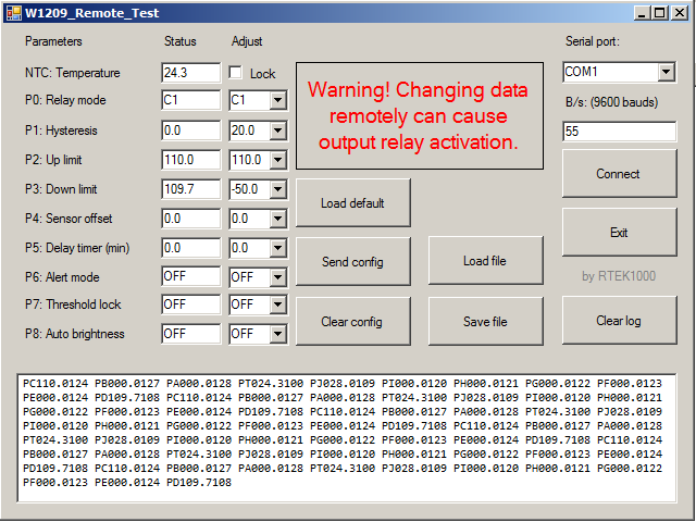
Windows app to manage settings:
-
Shows "HHH" or "LLL" on display if sensor fails, display flashing:
-
- If the sensor is disconnected, it shows "LLL".
-
- If the sensor is short circuited, it shows "HHH".
-
Code adaptation for Arduino IDE sketch.ino
-
Some bug fixes
-
Some functions added
-
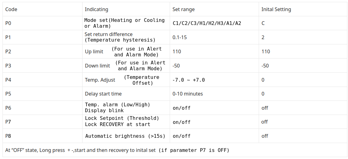
- Parameter P0: C1/C2/C3/H1/H2/H3/A1/A2
-
-
- C1: Cooler mode (hysteresis above Threshold)
-
-
-
- C2: Cooler mode (hysteresis below Threshold)
-
-
-
- C3: Cooler mode (hysteresis above and below Threshold)
-
-
-
- H1: Heater mode (hysteresis below Threshold)
-
-
-
- H2: Heater mode (hysteresis above Threshold)
-
-
-
- H3: Heater mode (hysteresis above and below Threshold)
-
-
-
- A1: Alarm mode (cause relay activation using the max. "P2" and min. parameters "P3")
-
-
-
-
- Temperature greater than the maximum value "P2": relay activated
-
-
-
-
-
- Temperature lower than the minimum value "P3": relay activated
-
-
-
-
- A2: Alarm mode (cause relay activation using the max. "P2" and min. parameters "P3")
-
-
-
-
- Temperature greater than the maximum value "P2": relay disabled
-
-
-
-
-
- Temperature lower than the minimum value "P3": relay disabled
-
-
-
- Parameter P1: Hysteresis (Degree hysteresis (°C) to toggle relay)
-
- Parameter P2: Up limit
-
-
- (Used in the alert indication; Activated in Parameter P6)
-
-
-
- (Used in Alarm mode Parameter P0: A1 and A2)
-
-
- Parameter P3: Down limit
-
-
- (Used in the alert indication; Activated in P6)
-
-
-
- (Used in Alarm mode Parameter P0: A1 and A2)
-
-
- Parameter P4: Temperature sensor offset
-
-
- (From -7.0 up to +7.0)
-
-
- Parameter P5: Delay time before activating the relay
-
-
- (From 0 to 10 minutes)
-
-
-
- (Does not affect relay deactivation, deactivation is immediate)
-
-
- Parameter P6: ON/OFF
-
-
- (Alert mode; Need setup Parameter P2 and P3; The display flashes when the temperature is outside the configured range.)
-
-
- Parameter P7: ON/OFF
-
-
- (Threshold value change access blocking)
-
-
-
- (Factory reset lockout with Up "+" and Down "-" keys)
-
-
- Parameter P8: ON/OFF
-
-
- (Automatic brightness reduction after 15 seconds)
-
-
Output status indication:
-
- Decimal point (DOT) right side off: Relay deactivated (contacts open)
-
- Decimal point (DOT) right side blinking: Relay deactivated (contacts open), but Waiting delay time programmed in Parameter P5
-
- Decimal point (DOT) right side on: Relay activated (contacts close)
-
- Factory reset:
-
-
- Set Parameter P7 in OFF
-
-
-
- Turn power supply Off
-
-
-
- Press and hold Up "+" and Down "-" keys
-
-
-
- Turn power supply On
-
-
-
- Wait for "rSt" to appear on the display
-
-
-
- Release all keys
-
-
-
- Wait for the current temperature to appear
-
-
Shows "HHH" or "LLL" on display if sensor fails, display flashing:
-
- If the sensor is disconnected, it shows "LLL"
-
- If the sensor is short circuited, it shows "HHH"
-
Troubleshoot:
-
- Microcontroller resetting: Try using a pull up resistor on the reset line
-
- Microcontroller no longer responds: High voltage return may have occurred through the relay LED
-
- The temperature does not correspond to the real: Try adjusting the offset Parameter P5 Try to replace the sensor Test using a resistor of NTC equivalent value for 25°C (10k) Try modifying the lookup table corresponding to the sensor
-
- Display flickering: Disconnect STlink programmer from SWIM port (next to display)
-
Note for Arduino IDE and Sduino core: Track the size of the code when uploading, The maximum I got was 93%
-
- (Sketch uses 7589 bytes (92%))
-
- (Bytes written: 8136)
-
- (Maximum is 8192 bytes)
-
Sduino core:
-
- Select STM8S Board / STM8S103F3 Breadout Board
-
- Programmer ST-link/V2
-
- Connect STlink: GND/SWIM/RST
-
ST-Link V2 Programming Example on Linux (check Bin folder):
-
- stm8flash -c stlinkv2 -p stm8s003?3 -w W1209-firmware-Arduino-table_R2_5k1_NTC_10k_B3950.hex
-
-
- Determine FLASH area
-
-
-
- STLink: v2, JTAG: v40, SWIM: v7, VID: 8304, PID: 4837
-
-
-
- Due to its file extension (or lack thereof), "W1209-firmware-Arduino-table_R2_5k1_NTC_10k_B3950.hex" is considered as INTEL HEX format!
-
-
-
- 8136 bytes at 0x8000... OK
-
-
-
- Bytes written: 8136
-
-
References:
-
-
Note:
-
- To enter the main configuration parameters menu:
-
-
- Press the SET key for a long time (for more than 5 seconds).
-
-
-
- Press the "+" or "-" keys to toggle between parameters "P0" through "P8".
-
-
-
- Short press SET key to enter the parameter.
-
-
-
-
- Press the "+" or "-" keys to change values.
-
-
-
- Long press SET key or no press (for 10 seconds), confirm and return automatically.
-
Note: Added delay for debounce, for fast increment hold key down.
-
Table of adjustable parameters:
There is an error in the electronic circuit that can kill the microcontroller, make the modification as soon as possible. Avoid using the board without modifying it. See here.

-
Other details can be seen in this post.
-
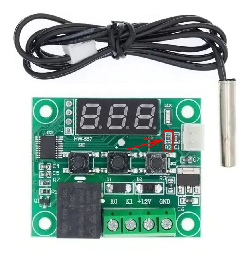
R2 is not the same for all boards:
-
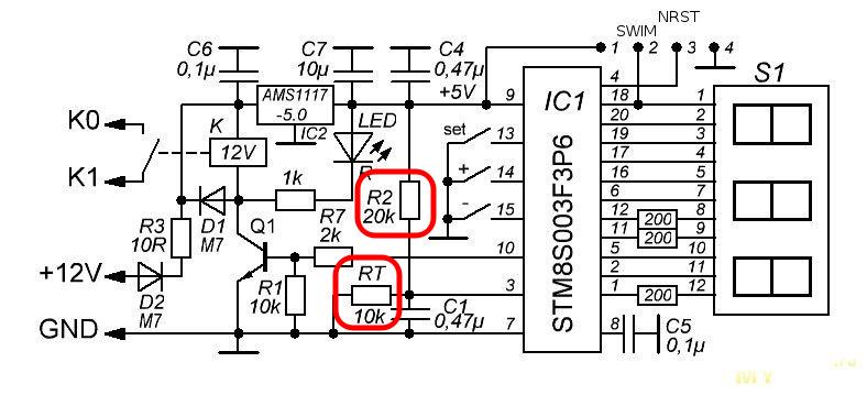
The generic schematic diagram shows the value of 20K ohms for R2:
-
R2 resistor: Some boards have a resistor value of 20k, others may have different values such as 5.1k, check the table in the adc.c file, if your board has a different value for R2 or for the sensor, it may be necessary to change the table rawADC[ ]:
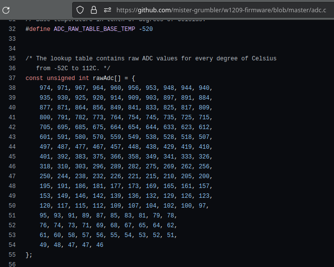
-
To generate a custom lookup table for a different sensor, you can use this tool:
-

Firmware to use the W1209 as a programmable timer: here
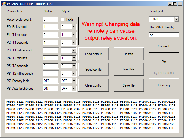
- There are 6 modes of operation (Looped or non-looped).
- Maximum time about 1000 minutes (about 16 hours and 40 minutes).
- Two-step timing (Times separated in minutes, seconds and milliseconds).
- Display automatically shows the most significant digits.
- Sensor input operating as a button.
- Remote Control (App Windows for tests).
- Note: This library is distributed in the hope that it will be useful, but WITHOUT ANY WARRANTY; without even the implied warranty of MERCHANTABILITY or FITNESS FOR A PARTICULAR PURPOSE. See the GNU Lesser General Public License for more details.
-
w1209-firmware
-
- The functional equivalent to the original firmware of "Digital Thermostat Module Model XH-W1209".
-
- The F.A.Q. page is available at https://github.com/mister-grumbler/w1209-firmware/wiki/FAQ
-
- Look at the list of issues to have an idea of what needs to be done for the initial release. https://github.com/mister-grumbler/w1209-firmware/issues