Project:
- Build a "kal-toh"-like (https://memory-alpha.fandom.com/wiki/Kal-toh) gaming platform.
- Electronic board game on a icosidodecahedron surface
- The edges of the icosidodecahedron can be selected and are iluminated
- Current implemented game is a "longest connect path" two player game.
Icosidodecahedron
- 60 edges
- 30 vertices
- 32 surfaces (12 pentagonal faces + 20 triangular faces)
Hardware:
- 60 sensors: Minus plate of a AA cell block, which is used as capacitive touch sensor fields
- 60 ilumnated edges: Sanded acrylic rod, iluminated via fiber opical wire from a 16x16 LED matrix
- 16x16 WS2812 LED Matrix
- Sensor & fiber optic holder: 3D printed https://github.com/olikraus/scad/tree/master/ikosidodekaeder
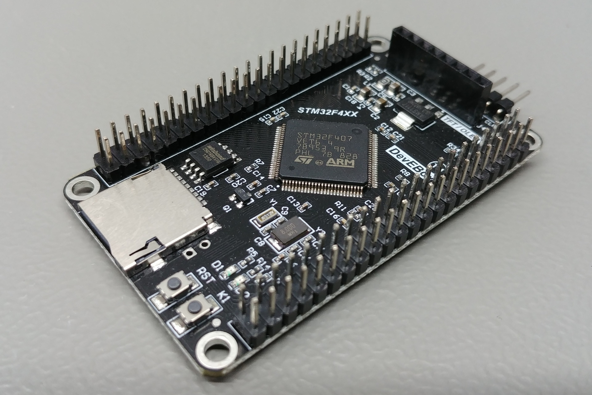
- STM32F407 development board (selected, because the STM32F407 has more than 60 GPIOs for the sensor input)
- Vertices: 3D printed https://github.com/olikraus/scad/tree/master/ikosidodekaeder
- 16x16 LED Matrix box: 3D printed https://github.com/olikraus/scad/tree/master/ikosidodekaeder
Software:
- Working example: https://github.com/olikraus/stm32f407/blob/main/ikosi_1/
- Arduino Environment (https://www.arduino.cc/)
- STM32Duino (https://github.com/stm32duino)
- WS2812B access via SPI1 written from scratch: https://github.com/olikraus/stm32f407/blob/main/spi_ws2812b/spi_ws2812b.ino
- Sensor Algorithm:
Line 1153 in 257317d
Result:

- STM32F407VET6 (192 KB RAM, 512 KB Flash)
- STM32duino Project (https://github.com/stm32duino/Arduino_Core_STM32):
- SystemCoreClock: 168 MHz
- APB2: 84 Mhz
- APB1: 42 Mhz
- Register Include File: https://raw.githubusercontent.com/stm32duino/Arduino_Core_STM32/main/system/Drivers/CMSIS/Device/ST/STM32F4xx/Include/stm32f407xx.h
- SysTick: https://github.com/ARM-software/CMSIS_5/blob/develop/CMSIS/Core/Include/core_cm4.h
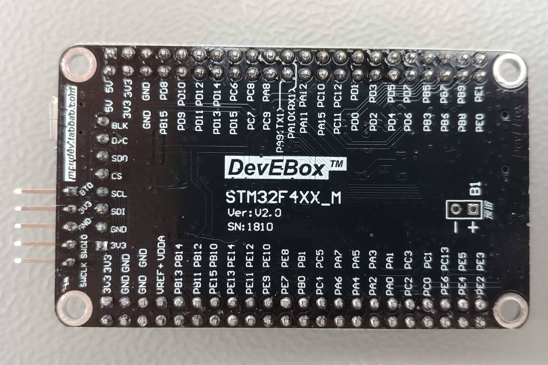
STM32F407 Board: https://stm32-base.org/boards/STM32F407VET6-STM32F4XX-M
- Button K1: PA0 (aktive high)
- LED D2: PA1 (Sink)
The above board doesn't allow to change to change the level at the BOOT0 pin (it is fixed to GND via a resistor). However BOOT0 is reqired to put the device into programming more for STM32Duino. This is done by pulling the BOOT0 pin to 3.3V via a small wire, soldered directly on the PCB:

- Four bits are used to form the waveform pattern for the WS2812B
Lines 355 to 363 in 257317d
- '1000' logical 0 for the WS2812, '1100' logical one for the WS2812B
- SPI 16 bit mode to transmit 4 bit for the WS2812B
- APB2 clock (84Mhz) is divided by 32 to get a SPI bitrate of 2.625 MHz = 380ns
- 380ns are close enough to the expected 400ns of the high pulse of the logical zero for the WS2812B
- The total transmission of one bit for the WS2812B is 4x380ns=1520ns (4x SPI bit)
- The WS2812B waveform pattern is generated "on-the-fly" by ISR procedure
Line 290 in 257317d
- Sensors connected to one GPIO port are checked in parallel (up to 16 sensors at a time)
- High clock speed of the ST32F407 (168 MHz): Internal pull down (60k) can be used as discharge resistor
- Algorithm:
Line 1153 in 257317d
- Charge GPIO pins (set output value to "1")
- Change GPIO pins to input mode with internal pulldown resistor
- Sample the low/high state all sensor lines for this port
- Use binary search to find the sample position high-low transition for each sensor line
- High sample index position (=long discharge time) means 'not touched'.
Arduino Pin Numbers:
PA0 Button K1
PA1 LED D2
PA2
PA3
PA4
PA5
PA6
PA7 SPI1_MOSI
PA8
PA9 USART1_TX
PA10 USART1_RX
PA11 USART1_CTS
PA12 USART1_RTS
PA13 SWDIO
PA14 SWDCLK
PA15
PB0
PB1
PB2
PB3
PB4
PB5
PB6
PB7
PB8
PB9
PB10
PB11
PB12 Pin seems to be connected to GND
PB13
PB14
PB15
PC0
PC1
PC2
PC3
PC4
PC5
PC6
PC7
PC8
PC9
PC10
PC11
PC12
PC13
PC14 Not on pin header for this board
PC15 Not on pin header for this board
PD0
PD1
PD2
PD3
PD4
PD5
PD6
PD7
PD8
PD9
PD10
PD11
PD12
PD13
PD14
PD15
PE0
PE1
PE2
PE3
PE4
PE5
PE6
PE7
PE8
PE9
PE10
PE11
PE12
PE13
PE14
PE15
PH0
PH1
Alternate pins number
PA0_ALT1
PA0_ALT2
PA1_ALT1
PA1_ALT2
PA2_ALT1
PA2_ALT2
PA3_ALT1
PA3_ALT2
PA4_ALT1
PA5_ALT1
PA6_ALT1
PA7_ALT1
PA7_ALT2
PA7_ALT3
PA15_ALT1
PB0_ALT1
PB0_ALT2
PB1_ALT1
PB1_ALT2
PB3_ALT1
PB4_ALT1
PB5_ALT1
PB8_ALT1
PB9_ALT1
PB14_ALT1
PB14_ALT2
PB15_ALT1
PB15_ALT2
PC0_ALT1
PC0_ALT2
PC1_ALT1
PC1_ALT2
PC2_ALT1
PC2_ALT2
PC3_ALT1
PC3_ALT2
PC4_ALT1
PC5_ALT1
PC6_ALT1
PC7_ALT1
PC8_ALT1
PC9_ALT1
PC10_ALT1
PC11_ALT1
Handler
WWDG_IRQHandler                   /* Window WatchDog              */
PVD_IRQHandler                    /* PVD through EXTI Line detection */
TAMP_STAMP_IRQHandler             /* Tamper and TimeStamps through the EXTI line */
RTC_WKUP_IRQHandler               /* RTC Wakeup through the EXTI line */
FLASH_IRQHandler                  /* FLASH                        */
RCC_IRQHandler                    /* RCC                          */
EXTI0_IRQHandler                  /* EXTI Line0                   */
EXTI1_IRQHandler                  /* EXTI Line1                   */
EXTI2_IRQHandler                  /* EXTI Line2                   */
EXTI3_IRQHandler                  /* EXTI Line3                   */
EXTI4_IRQHandler                  /* EXTI Line4                   */
DMA1_Stream0_IRQHandler           /* DMA1 Stream 0                */
DMA1_Stream1_IRQHandler           /* DMA1 Stream 1                */
DMA1_Stream2_IRQHandler           /* DMA1 Stream 2                */
DMA1_Stream3_IRQHandler           /* DMA1 Stream 3                */
DMA1_Stream4_IRQHandler           /* DMA1 Stream 4                */
DMA1_Stream5_IRQHandler           /* DMA1 Stream 5                */
DMA1_Stream6_IRQHandler           /* DMA1 Stream 6                */
ADC_IRQHandler                    /* ADC1, ADC2 and ADC3s         */
CAN1_TX_IRQHandler                /* CAN1 TX                      */
CAN1_RX0_IRQHandler               /* CAN1 RX0                     */
CAN1_RX1_IRQHandler               /* CAN1 RX1                     */
CAN1_SCE_IRQHandler               /* CAN1 SCE                     */
EXTI9_5_IRQHandler                /* External Line[9:5]s          */
TIM1_BRK_TIM9_IRQHandler          /* TIM1 Break and TIM9          */
TIM1_UP_TIM10_IRQHandler          /* TIM1 Update and TIM10        */
TIM1_TRG_COM_TIM11_IRQHandler     /* TIM1 Trigger and Commutation and TIM11 */
TIM1_CC_IRQHandler                /* TIM1 Capture Compare         */
TIM2_IRQHandler                   /* TIM2                         */
TIM3_IRQHandler                   /* TIM3                         */
TIM4_IRQHandler                   /* TIM4                         */
I2C1_EV_IRQHandler                /* I2C1 Event                   */
I2C1_ER_IRQHandler                /* I2C1 Error                   */
I2C2_EV_IRQHandler                /* I2C2 Event                   */
I2C2_ER_IRQHandler                /* I2C2 Error                   */
SPI1_IRQHandler                   /* SPI1                         */
SPI2_IRQHandler                   /* SPI2                         */
USART1_IRQHandler                 /* USART1                       */
USART2_IRQHandler                 /* USART2                       */
USART3_IRQHandler                 /* USART3                       */
EXTI15_10_IRQHandler              /* External Line[15:10]s        */
RTC_Alarm_IRQHandler              /* RTC Alarm (A and B) through EXTI Line */
OTG_FS_WKUP_IRQHandler            /* USB OTG FS Wakeup through EXTI line */
TIM8_BRK_TIM12_IRQHandler         /* TIM8 Break and TIM12         */
TIM8_UP_TIM13_IRQHandler          /* TIM8 Update and TIM13        */
TIM8_TRG_COM_TIM14_IRQHandler     /* TIM8 Trigger and Commutation and TIM14 */
TIM8_CC_IRQHandler                /* TIM8 Capture Compare         */
DMA1_Stream7_IRQHandler           /* DMA1 Stream7                 */
FSMC_IRQHandler                   /* FSMC                         */
SDIO_IRQHandler                   /* SDIO                         */
TIM5_IRQHandler                   /* TIM5                         */
SPI3_IRQHandler                   /* SPI3                         */
UART4_IRQHandler                  /* UART4                        */
UART5_IRQHandler                  /* UART5                        */
TIM6_DAC_IRQHandler               /* TIM6 and DAC1&2 underrun errors */
TIM7_IRQHandler                   /* TIM7                         */
DMA2_Stream0_IRQHandler           /* DMA2 Stream 0                */
DMA2_Stream1_IRQHandler           /* DMA2 Stream 1                */
DMA2_Stream2_IRQHandler           /* DMA2 Stream 2                */
DMA2_Stream3_IRQHandler           /* DMA2 Stream 3                */
DMA2_Stream4_IRQHandler           /* DMA2 Stream 4                */
ETH_IRQHandler                    /* Ethernet                     */
ETH_WKUP_IRQHandler               /* Ethernet Wakeup through EXTI line */
CAN2_TX_IRQHandler                /* CAN2 TX                      */
CAN2_RX0_IRQHandler               /* CAN2 RX0                     */
CAN2_RX1_IRQHandler               /* CAN2 RX1                     */
CAN2_SCE_IRQHandler               /* CAN2 SCE                     */
OTG_FS_IRQHandler                 /* USB OTG FS                   */
DMA2_Stream5_IRQHandler           /* DMA2 Stream 5                */
DMA2_Stream6_IRQHandler           /* DMA2 Stream 6                */
DMA2_Stream7_IRQHandler           /* DMA2 Stream 7                */
USART6_IRQHandler                 /* USART6                       */
I2C3_EV_IRQHandler                /* I2C3 event                   */
I2C3_ER_IRQHandler                /* I2C3 error                   */
OTG_HS_EP1_OUT_IRQHandler         /* USB OTG HS End Point 1 Out   */
OTG_HS_EP1_IN_IRQHandler          /* USB OTG HS End Point 1 In    */
OTG_HS_WKUP_IRQHandler            /* USB OTG HS Wakeup through EXTI */
OTG_HS_IRQHandler                 /* USB OTG HS                   */
DCMI_IRQHandler                   /* DCMI                         */
0                                 /* CRYP crypto                  */
HASH_RNG_IRQHandler               /* Hash and Rng                 */
FPU_IRQHandler                    /* FPU                          */
IRQ handler inside Arduino requires extern "C" prefix:
extern "C" void __attribute__ ((interrupt)) SPI1_IRQHandler(void)