Preparing files for running case studies using ATPDraw can become a time-consuming and human error-prone task. This software presents a toolbox for automatic generation and execution of ATP input files based on information obtained from a typical technical database of distribution utilities. This toolbox aims to reduce modeling time and susceptibility to human errors in the process of describing the grid in the software input file, which constitute the biggest obstacles to the extensive use of this program in real distribution grids.
You will need an installation of ATP/MingGW v1.24 or above. Usually, this installation can be found with ATPDraw installation. You can donwload this installer after registration here or here. An optimized and recompiled version can be requested via e-mail from the author, but it is necessary to prove the registration on the sites mentioned above.
To test if the ATP installation will be detected by the ATP Cases Generator, you will need to open the registry. Press ⊞+R and then type regedit, click in OK. Search for HKEY_LOCAL_MACHINE\SOFTWARE\ATPINST or HKEY_LOCAL_MACHINE\SOFTWARE\WOW6432Node\ATPINST. If any exists, ATP Cases Generator will find the ATP executable.
To install the software as a user to generate and simulate electrical grids only, follow the steps below. If you are looking for how to modify the code (You are probably not looking for this!), see Clone.
- Download the Setup.zip from the latest release (or any other release).
- Unzip the downloaded Setup.zip to any place using 7-Zip, WinRAR or any other software.
- In the unzipped folder, run the file setup.exe.
- Follow the installer steps.
After that, you should be ready to use the tool. To test if you can run it, open the command prompt pressing ⊞+R and then type cmd. In the command prompt, type atpcasesgenerator -v. If the command return the correct version of the ATP Cases Generator, you are ready to run it.
To modify the code follow the steps below. You will need the Git for Windows installed and Pipenv configured on Python.
- Open the command prompt pressing ⊞+R and then type
cmd. - Type
cd [PATH TO WHERE TO CLONE]. - Type
git clone https://github.com/munizrodrigo/atp-cases-generator.git. - Type
cd atp-cases-generator. - Type
pipenv install.
After that you can modify the code and run it using Pipenv.
Electric power system modeling for electromagnetic transients studies using specialized software such as Alternative Transients Program (ATP), can be a difficult and exhaustive task. For real electric distribution networks, for example, which typically have a large number of electric nodes, this modeling task becomes even more complicated, since a good part of these softwares requires filling up input text files with the description of each element of the electric three-phase network or the insertion of these elements in a graphical interface.
For the ATP software, there is the ATPDraw graphical interface, which works as a graphic preprocessor where the expert initially creates a representative diagram of the system using component models provided by ATP. However, the insertion of each electric network's element is a major source of complexity in the ATP utilization process, significantly increasing the time for the full description of the electric network, in addition to modifying the learning curve of engineers due to the fact of being a highly repetitive task that requires constant intervention and complete attention.
The automation of the manual data input procedure may have a strong impact on the engineer learning curve as well as in reducing the time spent on the electric network modeling, allowing the operator/engineer to focus on more productive tasks such as the evaluation of the results obtained by simulations and in decision-making tasks. Furthermore, errors due to human disability or loss of attention can be minimized by avoiding the repetition of actions.
Therefore, the following features are included in this tool.
- Automatically generate ATP input files from technical database from utilities.
- Execute and capture the results of simulation in ATP.
- Simulate larger grids through the grid equivalents and transmission/distribution line equivalents.
- Remove inconsistencies in the electrical grid due to the closure of cycles/loops.
- Generate interactive diagrams of electrical grids.
- Reduce the time to perform electromagnetic transients simulations in power distribution systems.
- Integrate ATP simulations into optimization and massive simulation programs due to the application operating on the command line.
ATP Cases Generator is a tool that operates from the command line. So, to use it, you need to open the command prompt pressing ⊞+R and then type cmd.
The basic usage of ATP Cases Generator consists on read a .txt input file, generate the ATP input files and save it on the output directory. The command to do this is as follows:
atpcasesgenerator --inp [INPUT FILE] --out [OUTPUT DIRECTORY]
Or:
atpcasesgenerator -i [INPUT FILE] -o [OUTPUT DIRECTORY]
Let's say that you have the file C:\ieee34.txt as an input file describing the grid to generate according to the input file documentation, and want to generate the corresponding .atp files in the directory C:\output. The command will be as follows:
atpcasesgenerator -i "C:\ieee34.txt" -o "C:\output"
The command will remain the same if the input file is in .xlsx format. However, if the format is .json, the correct command is as follows:
atpcasesgenerator -d "C:\ieee34.json" -o "C:\output"
If you want to see all the information in execution time, you can use the --print argument, or -p in short version.
atpcasesgenerator -i "C:\ieee34.txt" -o "C:\output" -p
If you want to generate the interactive electric diagrams, you can use the --graph command, or -g.
atpcasesgenerator -i "C:\ieee34.txt" -o "C:\output" -g
This command will create four files in the output directory:
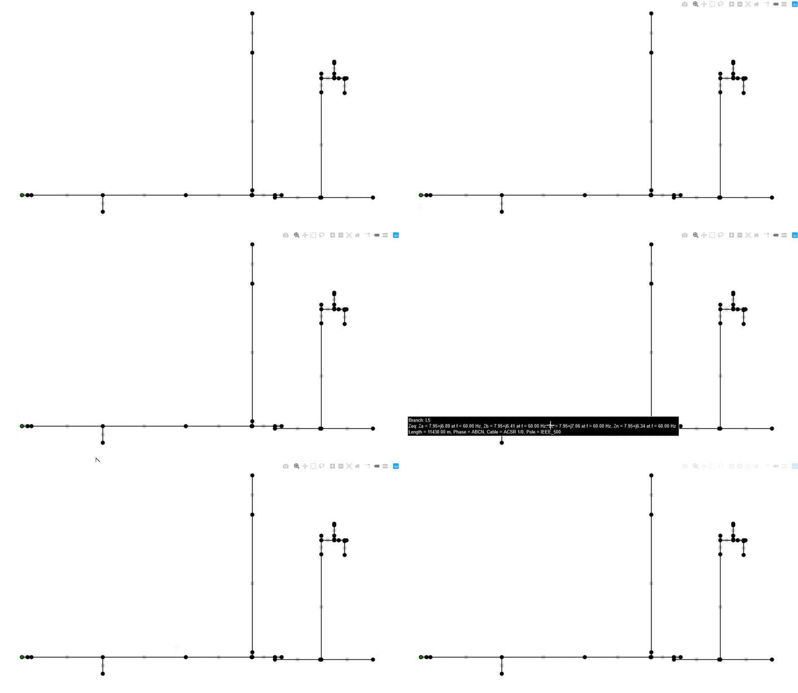
base_feeder.html, an interactive graph of the entire grid as can be seen here:
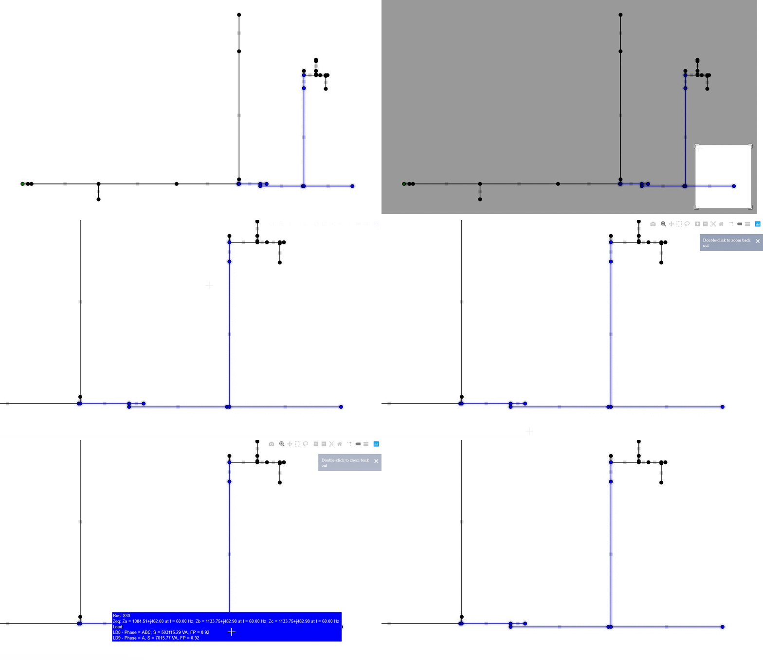
base_feeder.png, an static version ofbase_feeder.html.area_feeder.html, an interactive graph defining the coverage area.area_feeder.png, an static version ofarea_feeder.html.
Two forms of equivalent are available in this tool. The coverage area defines the external equivalent, while the internal equivalent corresponds to the line equivalents which are within the coverage area. Both are defined here and here.
To use the external equivalent, you have to define the central bus of the coverage area using the command --bus. After that, you need to define the number of adjacent buses to be added to the coverage area using the command --cov.The complete command is as follows:
atpcasesgenerator --inp [INPUT FILE] --out [OUTPUT DIRECTORY] --bus [CENTRAL BUS] --cov [NUMBER OF BUSES]
Or:
atpcasesgenerator -i [INPUT FILE] -o [OUTPUT DIRECTORY] -b [CENTRAL BUS] -c [NUMBER OF BUSES]
Using the example of IEEE 34-bus Feeder, whose .txt version can be found here, you can create the coverage area centered in bus "830" and composed of 10 buses adjacent to the central bus. The complete command is as follows:
atpcasesgenerator -i "C:\ieee34.txt" -o "C:\output" -b "830" -c 10
You can check area_feeder.html to see if the coverage area is in accordance with the desired, as seen below.
The internal equivalent excludes buses that are only passing buses, without elements such as load, capacitor and others. The complete definition of this equivalent can be found here. The commands are --limit, to define the maximum length of an equivalent line, and --line to use this kind of equivalent.
You can execute the generated .atp files and create the .lis and .pl4 outputs. Besides, you can create an .pckl file to read with Python using Pickle. To do this, just add the command --exec. The complete command is as follows:
atpcasesgenerator -i "C:\ieee34.txt" -o "C:\output" -e
You can use --step and --tmax to define the stepsize, or DELTAT, and the maximum simulation time, or TMAX, of the simulation. The complete command is as follows:
atpcasesgenerator -i "C:\ieee34.txt" -o "C:\output" -s 1e-8 -t 0.01
| Argument | Short Version | Description |
|---|---|---|
--help |
-h |
Show help message and exit. |
--version |
-v |
Show program's version and exit. |
--print |
-p |
Print the information to the console. |
--inp [FILE] |
-i [FILE] |
Set the path of input .xlsx or .txt file. |
--dict [FILE] |
-d [FILE] |
Set the path of input .json file with electric grid dictionary. |
--out [PATH] |
-o [PATH] |
Set the directory of output files. |
--bus [NAME] |
-b [NAME] |
Set the central bus of the coverage area. |
--cov [BUS] |
-c [BUS] |
Set the number of electric buses in the coverage area. |
--limit [LIM] |
-m [LIM] |
Set the maximum length in meters for the line equivalent. |
--line |
-l |
Use line equivalents. |
--graph |
-g |
Generate electric grid graphs. |
--exec |
-e |
Execute generated .atp file. |
--step [STEP] |
-s [STEP] |
Set simulation stepsize in seconds, equivalent to DELTAT variable on ATP. |
--tmax [TMAX] |
-t [TMAX] |
Set maximum simulation time in seconds, equivalent to TMAX variable on ATP. |
The format of this file can be .txt, separating categories for sorting by headers, or .xlsx separating categories by spreadsheets. This file contains the complete description of the electric grid under study according to the following categories of network elements: feeder, electric node, power supply, electric branch, capacitor bank, load, surge arrester, electric poles configuration, electric cable type, surge arrester type, among others.
The filling of this input file is based on information stored in the electric utilities technical databases, as previously mentioned. Most of the information in the electric utilities technical databases concerns the topological, geometric and constructive aspects of the electrical network. Electrical information as resistance, capacitance and inductance, for example, must be calculated from these initial information stored in the technical database.
You can find input file examples here.
To reduce the size of very large electrical grids, parts of the network are replaced by electrical equivalents. For this, it is necessary to define the creation of an area of interest for study, where the grid sections that are outside this area will be replaced by equivalent impedances.
First, it is worth mentioning that the ATP has some limitation to operate large electrical networks, since it has a limit of representing 6000 electrical nodes in the input cards, considering that all elements of the network, such as lightning arresters, transformers and banks capacitors, are considered electrical nodes for ATP. Although it is possible to create cards above this limit, ATP execution fails due to memory overflow, making them unusable.
For this reason, the concept of coverage area was created, which represents a subset of the electrical grid. In this case, instead of considering the entire electrical grid, only the electrical nodes contained in the coverage area will be represented in detail in the simulation studies.
To build the coverage area, it is necessary to define a node as the center of the coverage area and determine the number of neighboring nodes to be included. After that, the external equivalent is made, which consists of replacing the electrical grid and the equipment outside the coverage area by an equivalent impedance, considering the concentrated parameters, formed by the components: resistance, inductance and capacitance.
The line equivalent is applied to the electrical grid within the coverage area and consists of the elimination of internal nodes that do not have transformers, capacitors, lightning arresters or other shunt elements connected to them, having only the function of connecting nodes. To eliminate the connection nodes, it should be noted whether they have the same phase sequence and cable type and whether they are not root nodes, crossing nodes or leaf nodes. If so, the branches between these electrical nodes can be grouped together representing an equivalent branch whose resulting length is equal to the sum of the lengths of the branches individually, with the same distributed impedance.

