![]()

Bresser 5-in-1/6-in-1/7-in-1 868 MHz Weather Sensor Radio Receiver based on ESP32 and RFM95W/SX1276 - sends data to a LoRaWAN Network (e.g. The Things Network) Support for RP2040 (Arduino-Pico) has been added recently.
The RFM95W/SX1276 radio transceiver is used in FSK mode to receive weather sensor data and in LoRaWAN mode to connect to a LoRaWAN Network.
Auxiliary sensor data can be integrated via Bluetooth Low Energy (BLE), OneWire, UART, analog/digital inputs etc.
- Single 868 MHz Radio Transceiver for both Sensor Data Reception and LoRaWAN Connection
- Tested with The Things Network and Helium Network (EU868)
- Supports multiple 868 MHz Sensors (e.g. Weather Sensor and Soil Moisture Sensor or Indoor Thermometer/Hygrometer)
- See BresserWeatherSensorReceiver for supported sensors
- Low Power Design (using ESP32 Deep Sleep Mode / RP2040 Sleep State)
- Fast LoRaWAN Joining after Deep Sleep (using ESP32 RTC RAM / RP2040 Flash)
- ATC MiThermometer Bluetooth Low Energy Thermometer/Hygrometer Integration (optional)
- Theengs Decoder Bluetooth Low Energy Sensors Integration (optional)
- OneWire Temperature Sensor Integration (optional)
- ESP32/RP2040 Analog Digital Converter Integration (optional)
- A02YYUW / DFRobot SEN0311 Ultrasonic Distance Sensor (30...4500mm) (optional)
- Remote Configuration via LoRaWAN Downlink
-
Resumably Heltec WiFi LoRa32 V2 (confirmation wanted!!!)
-
Presumably Adafruit Feather ESP32-S2 with Adafruit LoRa Radio FeatherWing (confirmation wanted!!!)
-
Presumably Adafruit Feather ESP32 with Adafruit LoRa Radio FeatherWing (confirmation wanted!!!)
-
Thingpulse ePulse Feather with Adafruit LoRa Radio FeatherWing (see #56)
-
DFRobot FireBeetle ESP32 IoT Microcontroller with FireBeetle Cover LoRa Radio 868MHz
-
Adafruit Feather RP2040 with Adafruit LoRa Radio FeatherWing
See The Things Network's Big ESP32 + SX127x topic part 2 for some hardware options.
See Leonel Lopes Parente's collection of LoRa development boards pinout-diagrams.
You get a fully functional board (including antenna) which does not require any additional wiring for a reasonable price!
DFRobot FireBeetle ESP32 IoT (DFR0478) recomended due to its good low power design.
- Adafruit RFM95W LoRa Radio Transceiver Breakout (ADA3072) - 868/915 MHz version (868 MHz is used for both LoRaWAN and Bresser Weather Sensor in Europe) with RF connector (u.FL or SMA as desired)
or
- Delock 89769 - LoRa 868 MHz Antenna SMA plug 3 dBi omnidirectional has been used with good results
- EBYTE TX868-XP-100 868MHz SMA-J 3.5dBi High Gain Omnidirectional Antenna - larger, but better
Mains adapter or Li-Ion battery (with or without solar charger) - depending on desired operation time and duty cycle.
-
Install the Arduino ESP32 board package in the Arduino IDE -
Note: When using the ESP32 board package >=V2.0.5, you have to apply two fixes in arduino-lorawan and arduino-lmic, respectively (see below) -
Select the desired ESP32 board
-
Install all libraries as listed in the section Library Dependencies via the Arduino IDE Library Manager
-
Configure
Arduino/libraries/MCCI_LoRaWAN_LMIC_library/project_config/lmic_project_config.h:- select you appropriate region
#define CFG_sx1276_radio 1
-
Add the following line to
Arduino/libraries/MCCI_LoRaWAN_LMIC_library/project_config/lmic_project_config.h:#define LMIC_ENABLE_DeviceTimeReq 1(Otherwise requesting the time from the LoRaWAN network will not work, even if supported by the network.)
-
Apply fixes if using ESP32 board package >= v2.0.5
- mcci-catena/arduino-lorawan#204 (fixed in mcci-catena/arduino-lorawan v0.10.0)
- mcci-catena/arduino-lmic#714 (comment)
-
Clone (or download and unpack) the desired BresserWeatherSensorTTN release (Releases)
-
Load the sketch
BresserWeatherSensorTTN.inofrom the BresserWeatherSensorTTN directory -
Compile
| Library | r: required / o: optional |
|---|---|
| MCCI Arduino Development Kit ADK | r |
| MCCI LoRaWAN LMIC library | r |
| MCCI Arduino LoRaWAN Library | r |
| RadioLib | r |
| LoRa_Serialization | r |
| ESP32Time | r |
| BresserWeatherSensorReceiver | r |
| Preferences | r (RP2040) |
| ESP32AnalogRead | o |
| OneWireNg | o |
| DallasTemperature | o |
| NimBLE-Arduino + ATC_MiThermometer | o |
| NimBle-Arduino + Theengs Decoder | o |
| DistanceSensor_A02YYUW | o |
See package.json for required/tested versions.
- First you have to follow your LoRaWAN Network provider's instructions on how to configure/obtain the settings.
- Then configure the BresserWeatherSensorTTN software accordingly:
- Solution 1 (not recommended):
Configure the section starting with
// APPEUI, DEVEUI and APPKEYin BresserWeatherSensorTTN.ino - Solution 2 (recommended):
Configure the file secrets.h - refer to secrets.h.template as an example --
#define SECRETS

// deveui, little-endian
static const std::uint8_t deveui[] = { 0xAA, 0xBB, 0xCC, 0x00, 0x00, 0xDD, 0xEE, 0xFF };

// appeui, little-endian
static const std::uint8_t appeui[] = { 0x00, 0x00, 0x00, 0x00, 0x00, 0x00, 0x00, 0x00 };

// appkey: just a string of bytes, sometimes referred to as "big endian".
static const std::uint8_t appkey[] = { 0x11, 0x22, 0x33, 0x44, 0x55, 0x66, 0x77, 0x88, 0x99, 0xAA, 0xBB, 0xCC, 0xDD, 0xEE, 0xFF, 0x00 };
- Solution 1 (not recommended):
Configure the section starting with
By selecting a Board and a Board Revision (if available) in the Arduino IDE, a define is passed to the preprocessor/compiler. For the boards in the table below, the default configuration is assumed based in this define.
If you are not using the Arduino IDE, you can use the defines in the table below with your specific tool chain to get the same result.
If this is not what you need, you have to switch to Manual Configuration.
| Setup | Board | Board Revision | Define | Radio Module | Notes |
|---|---|---|---|---|---|
| LILYGO®TTGO-LORA32 V1 | "TTGO LoRa32-OLED" | "TTGO LoRa32 V1 (No TFCard)" | ARDUINO_TTGO_LORA32_V1 | SX1276 (HPD13A) | - |
| LILYGO®TTGO-LORA32 V2 | "TTGO LoRa32-OLED" | "TTGO LoRa32 V2" | ARDUINO_TTGO_LoRa32_V2 | SX1276 (HPD13A) | Wire DIO1 to GPIO33 |
| LILYGO®TTGO-LORA32 V2.1 | "TTGO LoRa32-OLED" | "TTGO LoRa32 V2.1 (1.6.1)" | ARDUINO_TTGO_LoRa32_v21new | SX1276 (HPD13A) | - |
| Heltec Wireless Stick | "Heltec Wireless Stick" | n.a. | ARDUINO_heltec_wireless_stick | SX1276 | - |
| LoRaWAN_Node | "FireBeetle-ESP32" | n.a. | ARDUINO_ESP32_DEV -> LORAWAN_NODE | SX1276 (RFM95W) | - |
| DFRobot FireBeetle ESP32 IoT Microcontroller with FireBeetle Cover LoRa Radio 868MHz | "FireBeetle-ESP32" | n.a. | ARDUINO_ESP32_DEV & FIREBEETLE_ESP32_COVER_LORA | SX1276 (LoRa1276) | Wiring on the cover: D2 to RESET D3 to DIO0 D4 to CS D5 to DIO1 |
| Adafruit Feather ESP32S2 with Adafruit LoRa Radio FeatherWing | "Adafruit Feather ESP32-S2" | n.a. | ARDUINO_ ADAFRUIT_FEATHER_ESP32S2 |
SX1276 (RFM95W) | No Bluetooth available! Wiring on the Featherwing: E to IRQ D to CS C to RST A to DI01 |
| Thingpulse ePulse Feather with Adafruit LoRa Radio FeatherWing | "Adafruit ESP32 Feather" | n.a. | ARDUINO_FEATHER_ESP32 | SX1276 (RFM95W) | Wiring on the Featherwing: E to IRQ D to CS C to RST A to DI01 see #55 |
| M5Stack Core2 with M5Stack Module LoRa868 | "M5Core2" | n.a. | ARDUINO_M5STACK_CORE2 | SX1276 (RA-01H) | Wiring on the LoRa868 Module: DIO1 to GPIO35 "M5Unified" must be installed M5.begin()is called to control power management |
| Adafruit Feather RP2040 with Adafruit LoRa Radio FeatherWing | "Adafruit Feather RP2040" | n.a. | ARDUINO_ADAFRUIT_FEATHER_RP2040 | SX1276 (RFM95W) | No Bluetooth available! Configuration: Choose an entry with "FS" in section Flash Size! Wiring on the Featherwing: E to IRQ D to CS C to RST A to DI01 |
If enabled in the Arduino IDE Preferences ("Verbose Output"), the preprosessor will provide some output regarding the selected configuration, e.g.
ARDUINO_ADAFRUIT_FEATHER_ESP32S2 defined; assuming RFM95W FeatherWing will be used
[...]
Receiver chip: [SX1276]
Pin config: RST->0 , CS->6 , GD0/G0/IRQ->5 , GDO2/G1/GPIO->11
Note: If you are using the same RF transceiver for sensor data reception and LoRaWAN connection, you must change the pin definitions in two places!
-
LoRaWAN Software Part
Change the default configuration in BresserWeatherSensorTTN.ino:
#define PIN_LMIC_NSS 14 #define PIN_LMIC_RST 12 #define PIN_LMIC_DIO0 4 #define PIN_LMIC_DIO1 16 #define PIN_LMIC_DIO2 17 -
BresserWeatherSensorReceiver Software Part
Change the default configuration in the directory Arduino/libraries/BresserWeatherSensorReceiver/src/WeatherSensorCfg.h!!!
Changing BresserWeatherSensorTTN/WeatherSensorCfg.h will have no effect!
#define PIN_RECEIVER_CS   14

// CC1101: GDO0 / RFM95W/SX127x: G0
#define PIN_RECEIVER_IRQ  4

// CC1101: GDO2 / RFM95W/SX127x: G1
#define PIN_RECEIVER_GPIO 16

// RFM95W/SX127x - GPIOxx / CC1101 - RADIOLIB_NC
#define PIN_RECEIVER_RST  12
The board specific default SPI pin definitions (MISO, MOSI and SCK) can be found in https://github.com/espressif/arduino-esp32/tree/master/variants
To configure other SPI pins than the default ones... is up to you. I.e. better use the default pins unless you have a really good reason not to do so and then only if you know what you're doing!
In BresserWeatherSensorTTNCfg.h:
- Select the desired LoRaWAN network by (un)-commenting
ARDUINO_LMIC_CFG_NETWORK_TTNorARDUINO_LMIC_CFG_NETWORK_GENERIC - Disable features which you do not want to use
- Configure the timing parameters (if you think this is needed)
- If enabled, configure your ATC MiThermometer's / Theengs Decoder's BLE MAC Address by by editing
KNOWN_BLE_ADDRESSES - Configure your time zone by editing
TZ_INFO - Configure the ADC's input pins, dividers and oversampling settings as needed
In BresserWeatherSensorTTN.ino, change the code starting with
//
// Encode sensor data as byte array for LoRaWAN transmission
//
LoraEncoder encoder(loraData);
Make sure that you do not exceed the size of the LoRaWAN uplink payload buffer loraData[PAYLOAD_SIZE]. The payload size is limited to 51 bytes by the LMIC library (for a good reason).
If you are using an Integration at the network side (such as an MQTT Integration), make sure you adjust your changes there as well - otherwise decoding the receiving/decoding the messages will fail.
See Debug Output Configuration in Arduino IDE
| Command / Response | Cmd | Port | Unit | Data0 | Data1 | Data2 | Data3 |
|---|---|---|---|---|---|---|---|
| CMD_SET_WEATHERSENSOR_TIMEOUT | 0xA0 | seconds | timeout[7:0] | ||||
| CMD_SET_SLEEP_INTERVAL | 0xA8 | seconds | interval[15: 8] | interval[ 7: 0] | |||
| CMD_SET_SLEEP_INTERVAL_LONG | 0xA9 | seconds | interval[15: 8] | interval[ 7: 0] | |||
| CMD_RESET_RAINGAUGE | 0xB0 | [flags] | |||||
| CMD_GET_CONFIG | 0xB1 | ||||||
| response: | 3 | seconds | ws_timeout[ 7: 0] | sleep_interval[15: 8] | sleep_interval[ 7: 0] | sleep_interval_long[15: 8] | |
| CMD_GET_DATETIME | 0x86 | ||||||
| response: | 2 | epoch | unixtime[31:24] | unixtime[23:16] | unixtime[15:8] | unixtime[7:0] | |
| CMD_SET_DATETIME | 0x88 | epoch | unixtime[31:24] | unixtime[23:16] | unixtime[15:8] | unixtime[7:0] |
- see scripts/ttn_downlink_formatter.js for syntax of commands and responses
- see The Things Network MQTT Integration and Payload Formatters
- Build command sequence as JSON string:
{"cmd": "CMD_SET_SLEEP_INTERVAL", "interval": 360} - Send command sequence via The Things Network Console

- Get epoch (e.g. from https://www.epochconverter.com) (Example: 1692729833); add an offset (estimated) for time until received (Example: + 64 seconds => 1692729897)
- Build command sequence as JSON string: {"cmd": "CMD_SET_DATETIME", "epoch": 1692729897}
- Send command sequence via The Things Network Console
- Convert interval to hex: 360 = 0x0168
- Build command sequence: "CMD_SET_SLEEP_INTERVAL 360 secs" -> 0xA8 0x01 0x68
- Send command sequence via The Things Network Console

- Get epoch (e.g. from https://www.epochconverter.com/hex) (Example: 0x63B2BC32); add an offset (estimated) for time until received (Example: + 64 / 0x40 seconds => 0x63B2BC72)
- Build command sequence: "CMD_SET_DATETIME 0x63B2BC72" -> 0x88 0x63 0xB2 0xBC 0x72
- Send command sequence via The Things Network Console
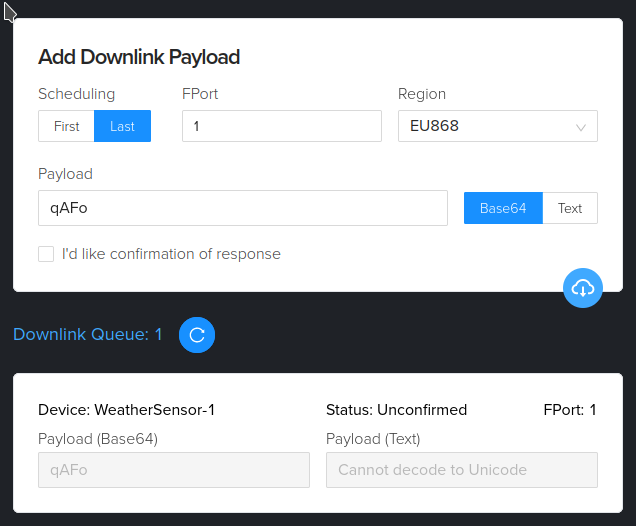
To be done
- Convert interval to hex: 360 = 0x0168
- Build command sequence: "CMD_SET_SLEEP_INTERVAL 360 secs" -> 0xA8 0x01 0x68
- Convert command sequence to Base64 encoding: 0xA8 0x01 0x68 -> "qAFo" (Base64 Guru)
- Send command sequence via Helium Console
- Get epoch (e.g. from https://www.epochconverter.com/hex) (Example: 0x63B2BC32); add an offset (estimated) for time until received (Example: + 64 / 0x40 seconds => 0x63B2BC72)
- Build command sequence: "CMD_SET_DATETIME 0x63B2BC72" -> 0x88 0x63 0xB2 0xBC 0x72
- Convert command sequence to Base64 encoding: 0x88 0x63 0xB2 0xBC 0x72 -> "iGOyvHI="
- Send command sequence e.g. via Helium Console
Decode uplink payload (a sequence of bytes) into data structures which are readable/suitable for further processing.
In The Things Network Console:
- Go to "Payload formatters" -> "Uplink"
- Select "Formatter type": "Custom Javascript formatter"
- "Formatter code": Paste scripts/ttn_uplink_formatter.js
- Apply "Save changes"

Encode downlink payload from JSON to a sequence of bytes.
In The Things Network Console:
- Go to "Payload formatters" -> "Downlink"
- Select "Formatter type": "Custom Javascript formatter"
- "Formatter code": Paste scripts/ttn_downlink_formatter.js
- Apply "Save changes"
Note: The actual payload depends on the options selected in the Arduino software - the decoder must be edited accordingly (add or remove data types and JSON identifiers - see scripts/ttn_uplink_formatter.js line 316ff). The configuration dependent part of the decoder can be created with a C++ preprocessor and the Python script generate_decoder.py.
TTN provides an MQTT broker. How to receive and decode the payload with an MQTT client - see https://www.thethingsnetwork.org/forum/t/some-clarity-on-mqtt-topics/44226/2
V3 topic:
v3/<ttn app id><at symbol>ttn/devices/<ttn device id>/up
v3 message key field jsonpaths:
<ttn device id> = .end_device_ids.device_id
<ttn app id> = .end_device_ids.application_ids.application_id  // (not including the <at symbol>ttn in the topic)
<payload> = .uplink_message.frm_payload
JSON-Path with Uplink-Decoder (see scripts/ttn_uplink_formatter.js)
.uplink_message.decoded_payload.bytes.<variable>
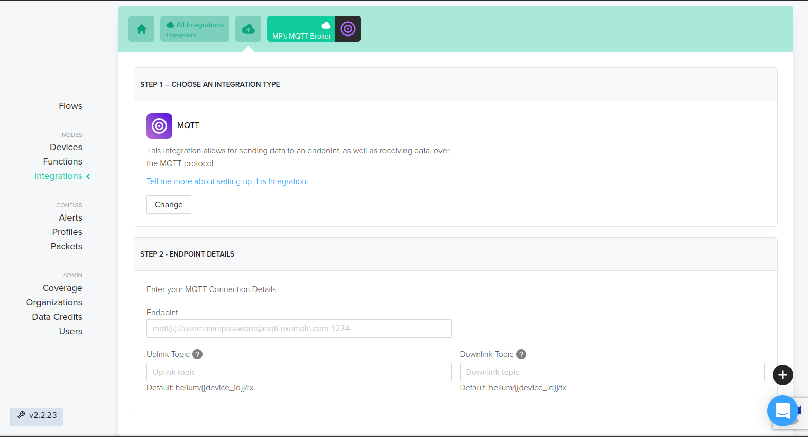
Please refer to https://docs.helium.com/use-the-network/console/integrations/mqtt/.
Add an MQTT integration in the Helium console - the "Endpoint" is in fact an MQTT broker you have to provide:
Add scripts/helium_decoder.js in the Helium console as custom function:
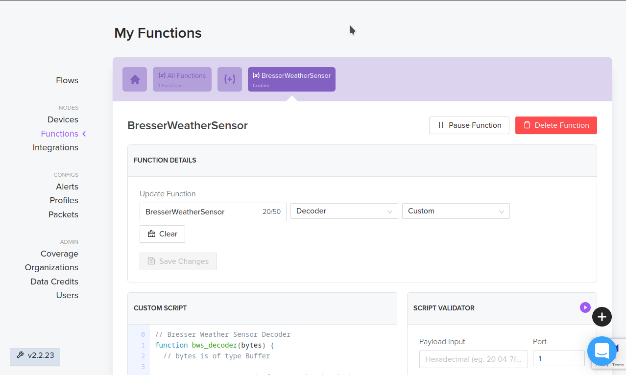
Note: The actual payload depends on the options selected in the Arduino software - the decoder must be edited accordingly (add or remove data types and JSON identifiers).
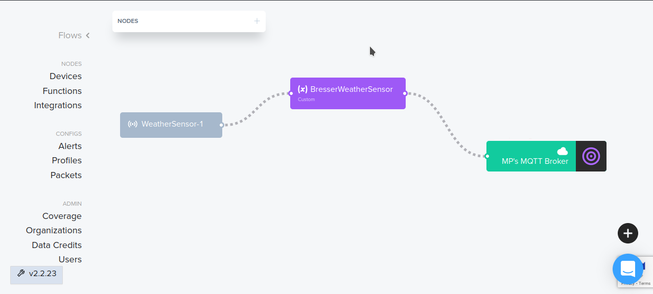
Add your function to the flow:
Example decoder output (JSON):
rx = {[...],"decoded":{"payload":{"air_temp_c":"13.5","battery_v":4197,"humidity":72,"indoor_humidity":53,"indoor_temp_c":"21.7","rain_day":"0.0","rain_hr":"0.0","rain_mm":"480.8","rain_mon":"0.0","rain_week":"0.0","soil_moisture":0,"soil_temp_c":"-30.0",
"status":{"ble_ok":true,"res":false,"rtc_sync_req":true,"runtime_expired":true,"s1_batt_ok":false,"s1_dec_ok":false,"ws_batt_ok":true,"ws_dec_ok":true},
"supply_v":4210,"water_temp_c":"-30.0","wind_avg_meter_sec":"1.9","wind_direction_deg":"282.0","wind_gust_meter_sec":"2.0"},
"status":"success"}, [...]


YouTube Video: Get started for free with LoRaWaN on The Things Network and Datacake IoT Platform
Basic example for a single Weather Sensor uplink to The Things Network.
The Things Network uplink formatter for the full set of features provided by the default SW configuration. Includes decoding of response messages triggered by uplink command messages.
The Things Network downlink formatter for sending commands as JSON strings to the device.
Variant of ttn_uplink_formatter.js which supports the ultrasonic distance sensor, but neither the lightning sensor nor response messages.
Predecessor of ttn_uplink_formatter.js without support of response messages. deprecated, will eventually be deleted
Variant of ttn_uplink_formatter.js for Helium Network, currently without support of response messages.
Equivalent of ttn_uplink_formatter.js for Datacake, currently without support of response messages.
https://matthias-bs.github.io/BresserWeatherSensorTTN/index.html
Based on
- BresserWeatherSensorReceiver by Matthias Prinke
- RadioLib by Jan Gromeš
- MCCI LoRaWAN LMIC library by Thomas Telkamp and Matthijs Kooijman / Terry Moore, MCCI
- MCCI Arduino LoRaWAN Library by Terry Moore, MCCI
- Lora-Serialization by Joscha Feth
- ESP32Time by Felix Biego
- ESP32AnalogRead by Kevin Harrington (madhephaestus)
- OneWireNg by Piotr Stolarz
- DallasTemperature / Arduino-Temperature-Control-Library by Miles Burton
- NimBLE-Arduino by h2zero
- Theengs Decoder by Theengs Project
- DistanceSensor_A02YYUW by Pablo Portela
- Preferences by Volodymyr Shymanskyy
This project is in no way affiliated with, authorized, maintained, sponsored or endorsed by Bresser GmbH or any of its affiliates or subsidiaries.