
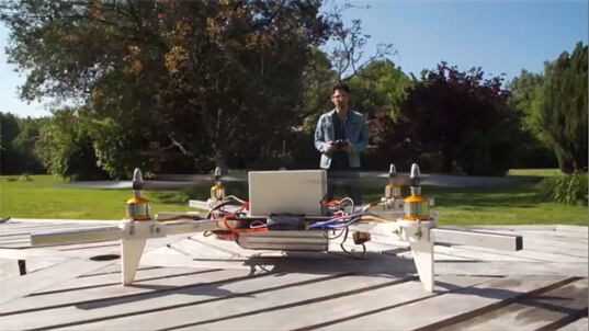
This Arduino sketch provides a flight controller for an X quadcopter based on an Arduino Uno board and the MPU6050 sensor.
Basically, this automation routine is an implementation of a digital PID with a refresh rate of 250Hz. The method used to calculate PID coefficients is Ziegler Nichols method. The frame of the quadcopter is based on the F450.
You can use this to calibrate your ESCs.
A detailed article is available here (in french).
(i) Currently under active development.
Arduino libraries:
       +-------------------------+
       |        MPU-6050         |
       |                         |
       | 3V3  SDA  SCL  GND  INT |
       +--+----+----+----+----+--+
          |    |    |    |
          |    |    |    |
+---------+----+----+----+----------------+
|        3.3V  A4   A5  GND               |
|                                         |
|                                         |
|                 Arduino Uno             |
|                                         |
| #4   #5   #6   #7   #8   #9  #10   #11  |
+--+----+----+----+----+----+----+----+---+
   |    |    |    |    |    |    |    |
  (M1) (M2) (M3) (M4)  |    |    |    |
                       |    |    |    |
                       |    |    |    |
                    +--+----+----+----+---+
                    | C1   C2   C3   C4   |
                    |                     |
                    |     RF Receiver     |
                    +---------------------+

Legend:
Mx: Motor X
Cx: Receiver channel x
By default, this sketch uses the mode 2 for RF remote, according to the following picture:
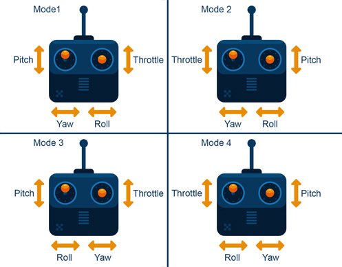
The channel mapping is then:
| Channel | Command |
|---|---|
| 1 | ROLL |
| 2 | PITCH |
| 3 | THROTTLE |
| 4 | YAW |
To change the channel mapping, update the function configureChannelMapping according to your needs:
void configureChannelMapping() {
    mode_mapping[YAW]      = CHANNEL4;
    mode_mapping[PITCH]    = CHANNEL2;
    mode_mapping[ROLL]     = CHANNEL1;
    mode_mapping[THROTTLE] = CHANNEL3;
}The default PID coeffcient values might work for an F450-like quadcopter. However, you can tune them in the global variable declaration section:
// PID coefficients
float Kp[3] = {4.0, 1.3, 1.3};    // P coefficients in that order : Yaw, Pitch, Roll
float Ki[3] = {0.02, 0.04, 0.04}; // I coefficients in that order : Yaw, Pitch, Roll
float Kd[3] = {0, 18, 18}; // D coefficients in that order : Yaw, Pitch, Roll Front
(1) (2) x
\ / z ↑
X \|
/ \ +----→ y
(3) (4)
- Motor 1: front left - clockwise
- Motor 2: front right - counter-clockwise
- Motor 3: rear left - clockwise
- Motor 4: rear left - counter-clockwise
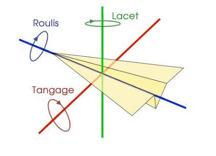
- Left wing up implies a positive roll
- Nose up implies a positive pitch
- Nose right implies a positive yaw
The MPU6050 must be oriented as following:
- X axis: roll
- Y axis: pitch
- Z axis: yaw
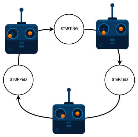
This sketch comes with a safety process: to start the quadcopter, move the left stick of the remote in the bottom left corner. Then move it back in center position.
To stop the quadcopter, move the left stick in the bottom right corner.
If you need to print debug messages, make sure to init Serial at 57600 bauds:
void setup() {
  Serial.begin(57600);
  // ...
}

void loop() {
  Serial.println(measures[ROLL]);
  // ...
}