The latest project address of the kit will simplify all processes, please refer to the link here: https://github.com/limengdu/mmwave-kit-external-components/tree/main
This article will guide you through the installation of the ESPHome service in your own Home Assistant environment. By using the WiFi function of the XIAO ESP32C3, you will be able to connect your XIAO to the Home Assistant as part of your home terminal in a very smooth way.
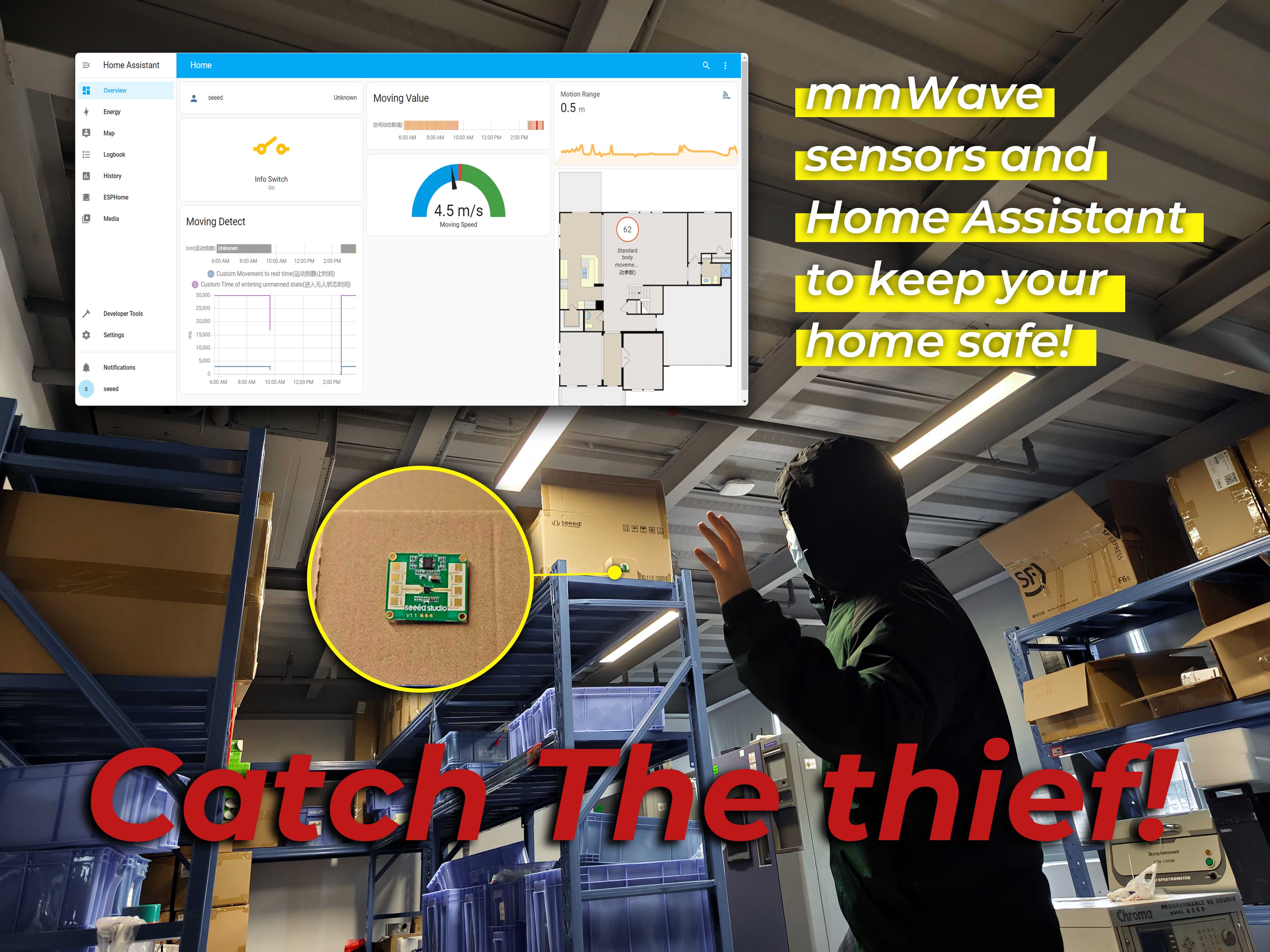
In addition, we will build a Home Assistant with human presence detection in combination with the most popular 24GHz mmWave Human Static Presence Module Lite.
:::tip As of 31 July 2023, the previous issue that would cause the radar to completely die has now been fixed, so please update the library files and configurator for this tutorial species to work properly. :::
If you want to follow this tutorial through everything, you will need to prepare the following.
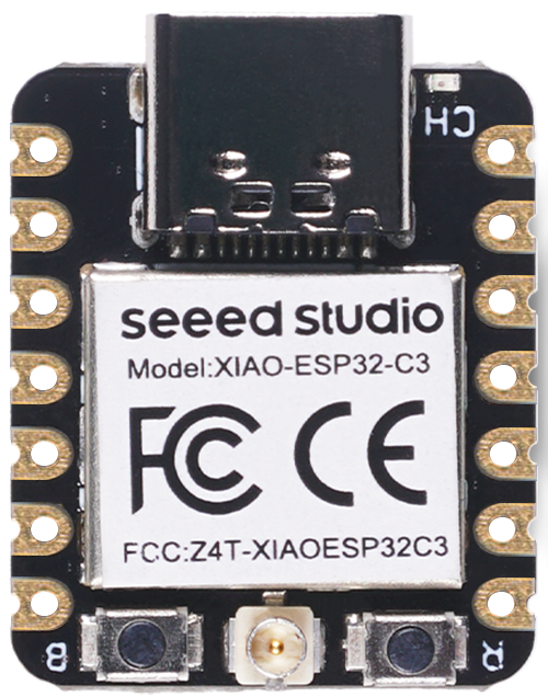
| XIAO ESP32C3 | 24GHz mmWave Human Static Presence Module Lite |
|---|---|
 |
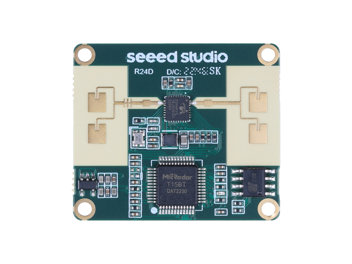 |
The ultimate goal of this project is to deploy 24GHz mmWave Human Static Presence Module Lite in the Home Assistant.
We have written complete configuration files and libraries for the 24GHz mmWave Human Static Presence Module Lite to facilitate your rapid deployment of sensor to Home Assistant in this project.
The content of this tutorial will broadly go through the following steps.
- Select your Home Assistant environment
- Install and cofigure ESPHome in Home Assistant
- Configure the XIAO ESP32C3 and ESPHome connection
- Configure Home Assistant Panel
Of course, if you are interested in how the XIAO ESP32C3 uses Grove in the Home Assistant, you can read this chapter directly.
In this routine, we will not expand on how to install the Home Assistant environment, we will assume that you already have a working Home Assistant device.
If you wish to learn how to install Home Assistant, then you can refer to the official tutorial. We strongly recommend that you install Home Assistant using an x86 device as this is the most user friendly way for you to install Home Assistant with Supervised.
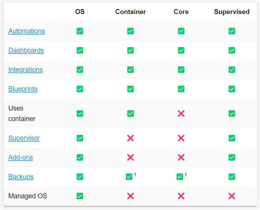
According to the table above, it is most appropriate to install Home Assistant OS and Home Assistant Supervised, which will take a lot of hassle off your hands. If you are running Home Assistant on Docker with OpenWRT (e.g. using LinkStar H68K), please don't worry, we will also provide you with a detailed reference on how to do this.
We have also written how to install Home Assistant for some of Seeed Studio products, please refer to them.
- Getting Started with Home Assistant on ODYSSEY-X86
- Getting Started with Home Assistant on reTerminal
- Getting Started with Home Assistant on LinkStar H68K/reRouter CM4
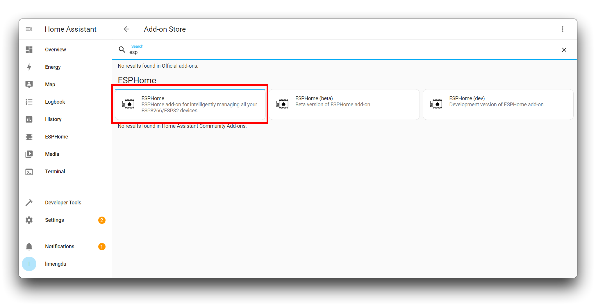
- Scenario 1: ESPHome installation under Home Assistant OS (with Add-on Store)
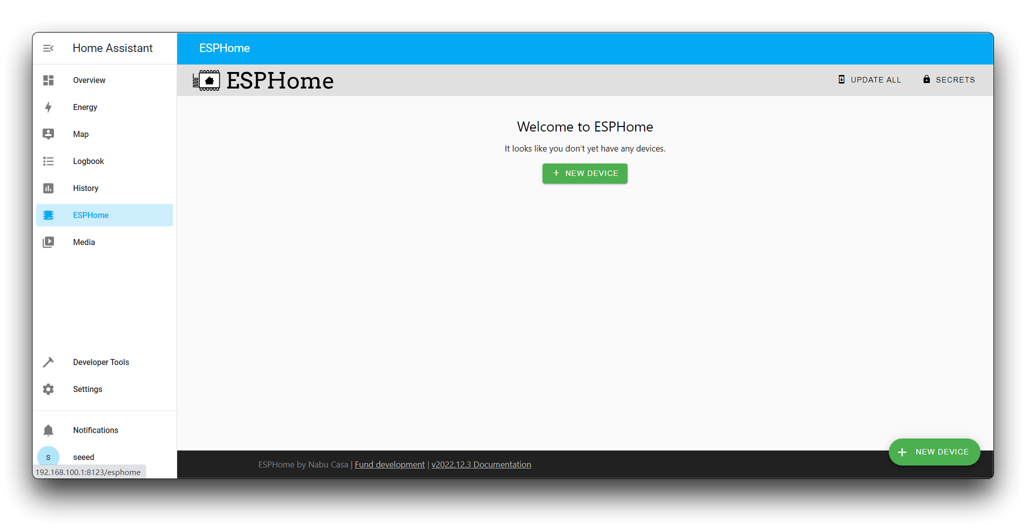
If you have the Home Assistant OS installed, it has an Add-on Store, which makes it much easier to install ESPHome.
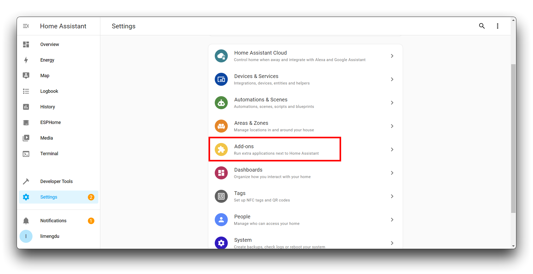
In the Add-on Store, you can search for and install ESPHome.
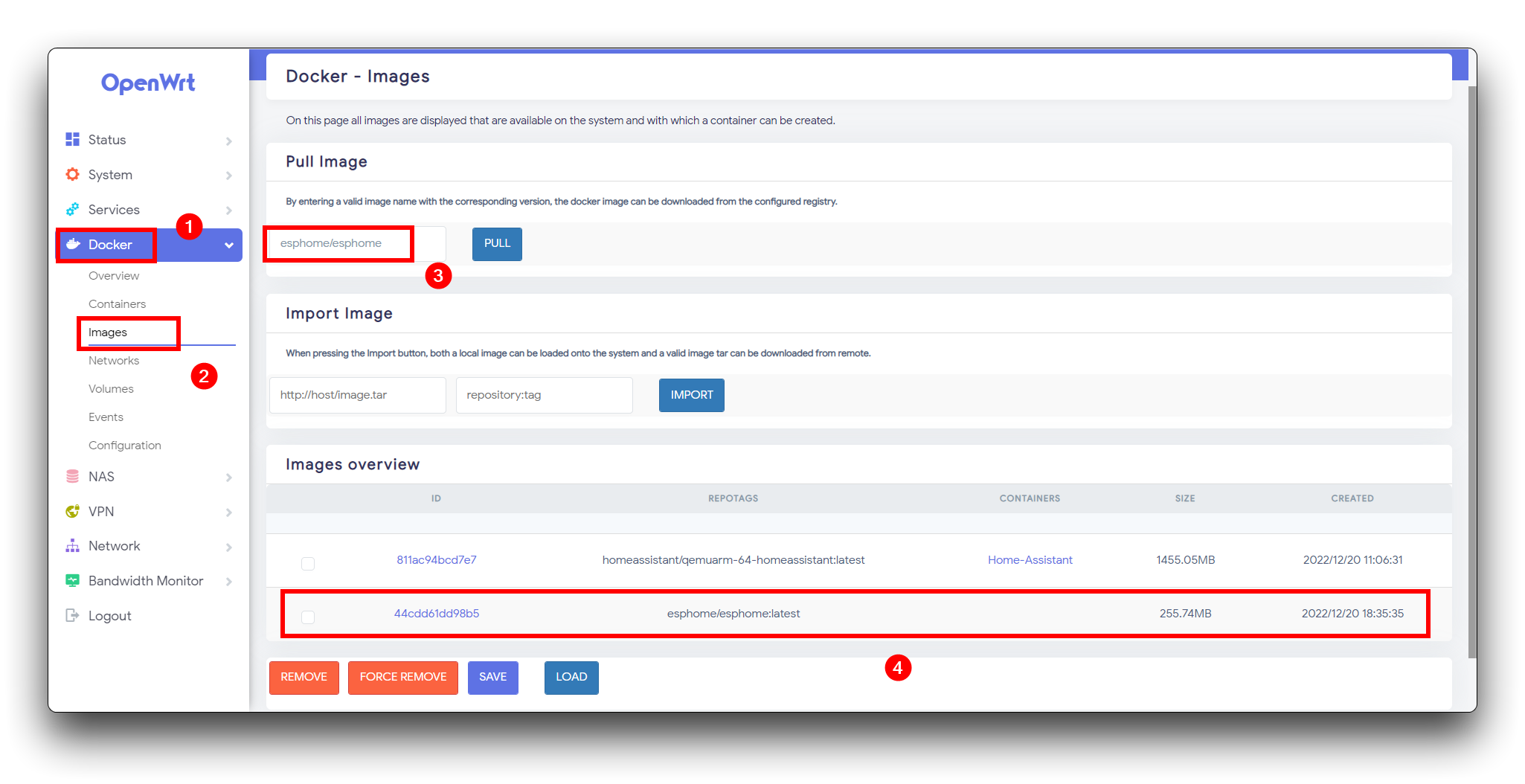
- Scenario 2: ESPHome installed under Home Assistant under OpenWRT Docker/Docker (without Add-on Store)
As we are installing the Home Assistant Container, we cannot simply download the ESPHome service via the Add-on Store, so a compromise is needed.
We need to download the ESPHome image.
esphome/esphome:latest
On the page where the container is created, we need to make some simple settings.
- Container Name: your container name
- Docker Image: choose just downloaded esphome image
- Network: choose host mode
- Environment Variables(-e): your environment variable
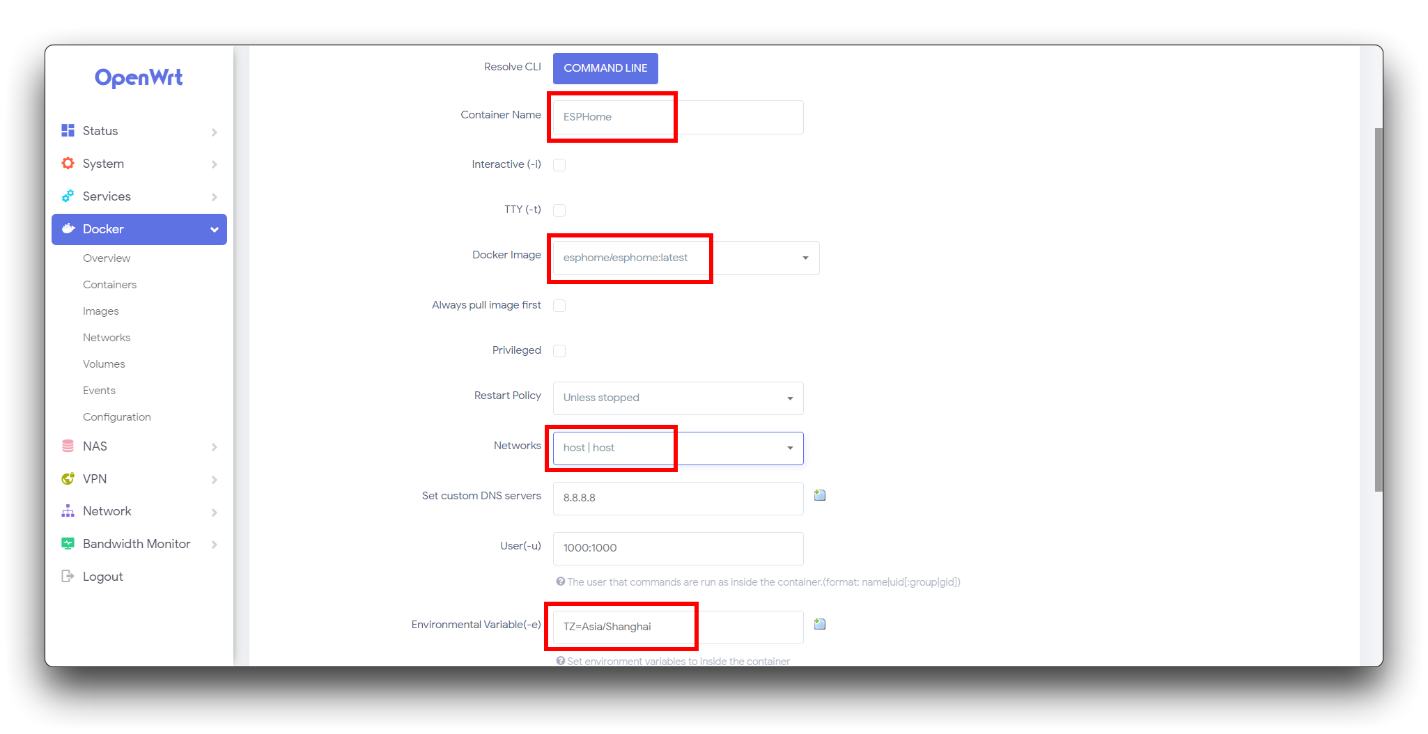
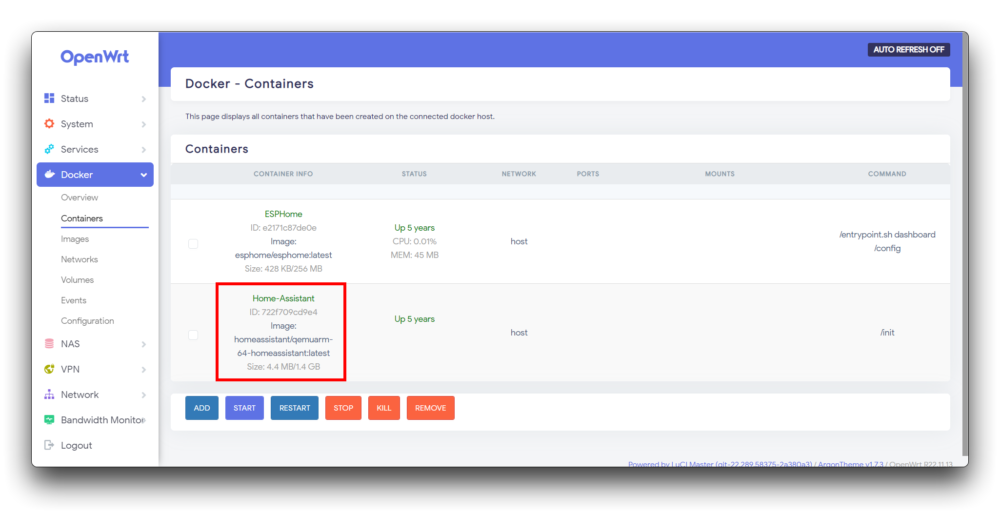
Once you have filled in the above, save and apply. You will see that the Container has been created. You also need to start it.
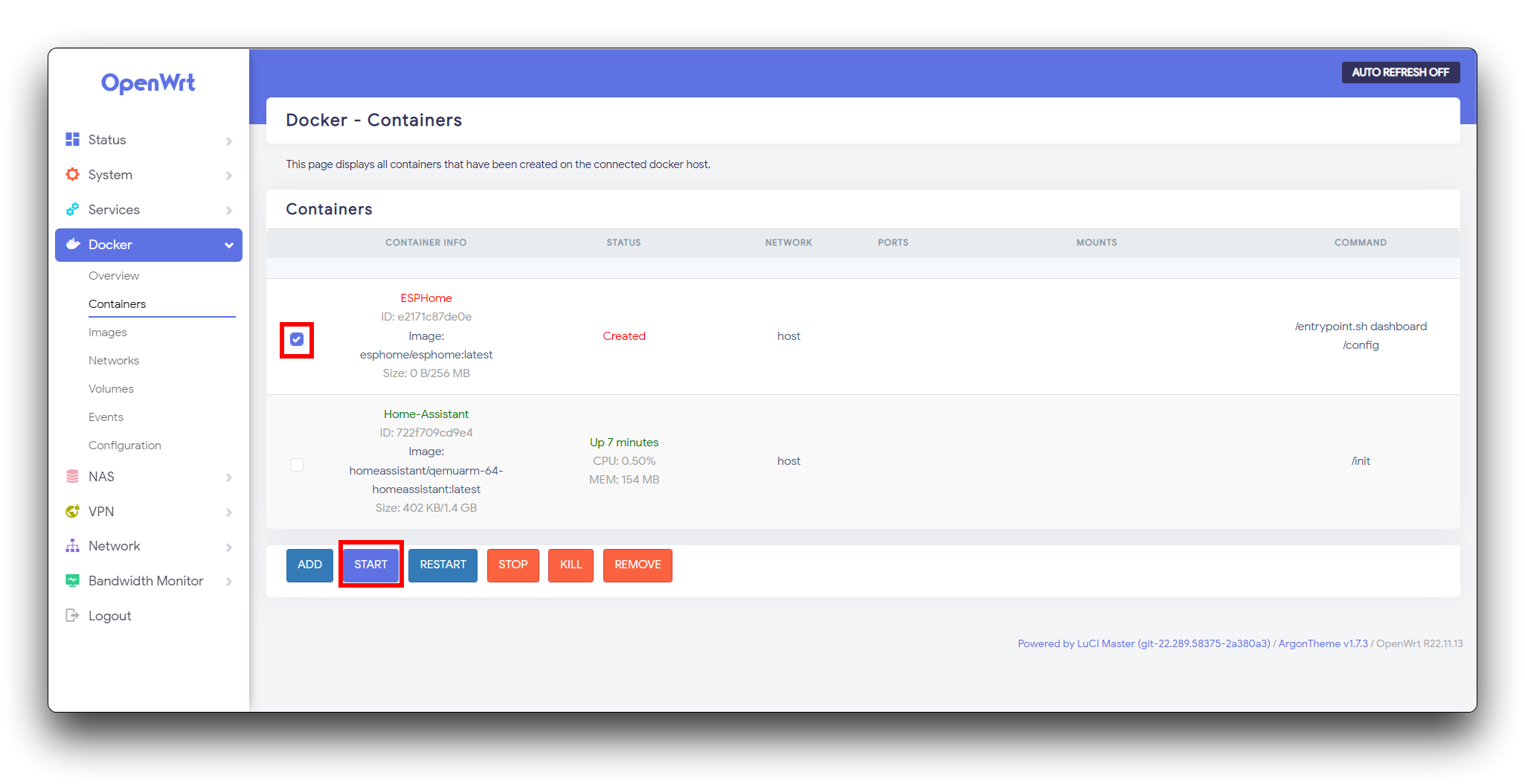
In order to achieve the same effect as downloading ESPHome in Home Assistant, we need to modify the configuration file under Home Assistant.
Go to the Home Assistant Container.
We go to the terminal in Home Assistant.
Enter the following command in the terminal.
vi configuration.yamlAdd following content to the end of configuration.yaml.
# Example configuration.yaml entry
panel_iframe:
  esphome:
    title: "ESPHome"
    url: "http://192.168.100.1:6052"
    icon: mdi:chip
Exit the docker container by type exit in the Home Assistant Container shell. Once this is done, we restart the Home Assistant container.
Create a new browser page, enter address http://homeassistant:8123/ and enter your Home Assistant account and you will see ESPHome appear in the toolbar on the left.
The goal of our tutorial is to be able to see the data information of the 24GHz mmWave Human Static Presence Module Lite in the Home Assistant dashboard.
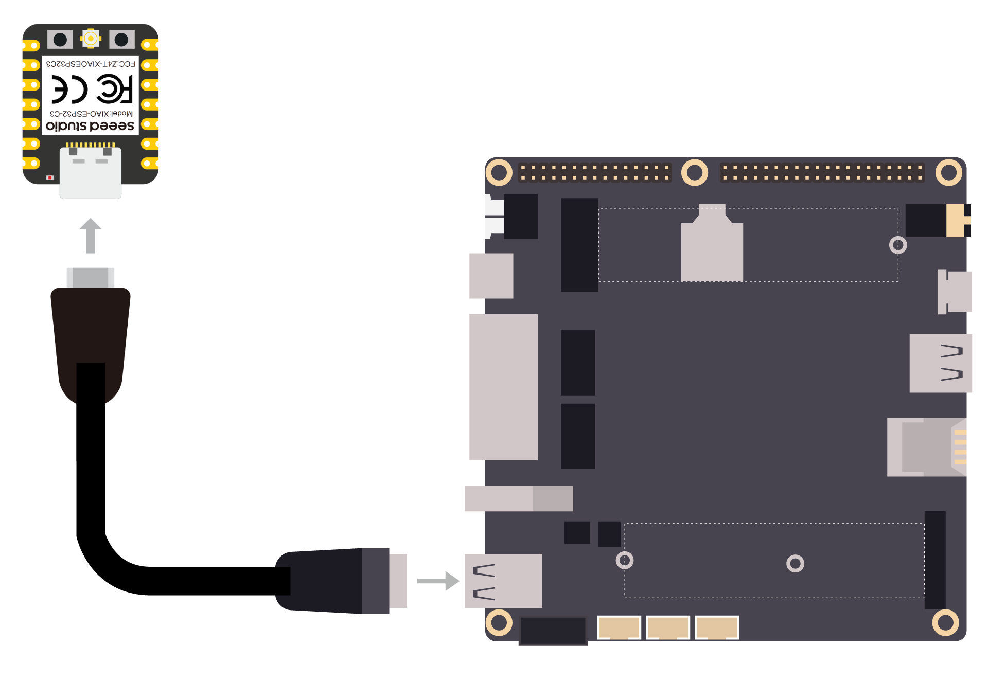
Connect the device to the computer through the main board. The wiring diagram is shown in the table below.
 |
||
| XIAO ESP32C3 | 24GHz mmWave Human Static Presence Module Lite |
|
| 5V | --> | 5V |
| GND | --> | GND |
| D2 | --> | RX |
| D3 | --> | TX |
- Scenario 1: ESPHome installation under Home Assistant OS (with Add-on Store)
In order to download some files from Home Assistant, we need to use the Terminal & SSH service.
Please ensure that you have enabled Advanced Mode.

Then you can search for the add-on Terminal & SSH in the Add-on Store, please install it.

Once the installation is complete, you will be able to see the Terminal tool in the left-hand toolbar, which you can access by clicking on it in the bash window.

Enter the following command in the terminal.
cd /config/esphome/
curl -o R24dvd_new.h https://files.seeedstudio.com/wiki/homs-xiaoc3-linkstar/R24dvd_new.h
In this way, you have installed the dependencies needed for the sensors under the specified path in Home Assistant.
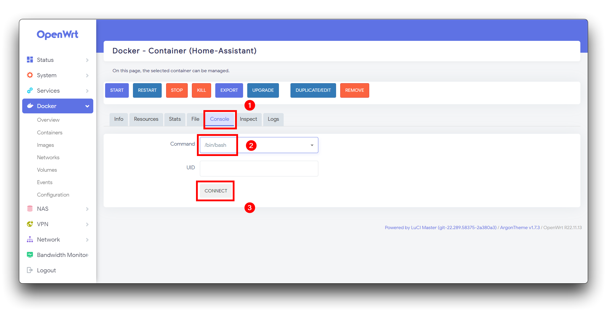
- Scenario 2: ESPHome installed under Home Assistant under OpenWRT Docker/Docker (without Add-on Store)
Click on the ESPHome Container.

We go to the terminal in ESPHome.

Enter the following command in the terminal.
curl -o R24dvd_new.h https://files.seeedstudio.com/wiki/homs-xiaoc3-linkstar/R24dvd_new.h
Wait a few moments and the sensor library will be downloaded to the ESPHome Container root directory.

I am sure that your Home Assistant has already done the work of getting into the network, for example by connecting to your device via a network cable. All you need to do then is simply to turn on a local network (e.g. WiFi) so that the XIAO ESP32C3 can also connect to this network.
I will use the LinkStar H68K as an example below. My aim is to get the XIAO connected to the LinkStar H68K's hotspot.
In the Network tab in OpenWRT, select Wireless --> ADD.
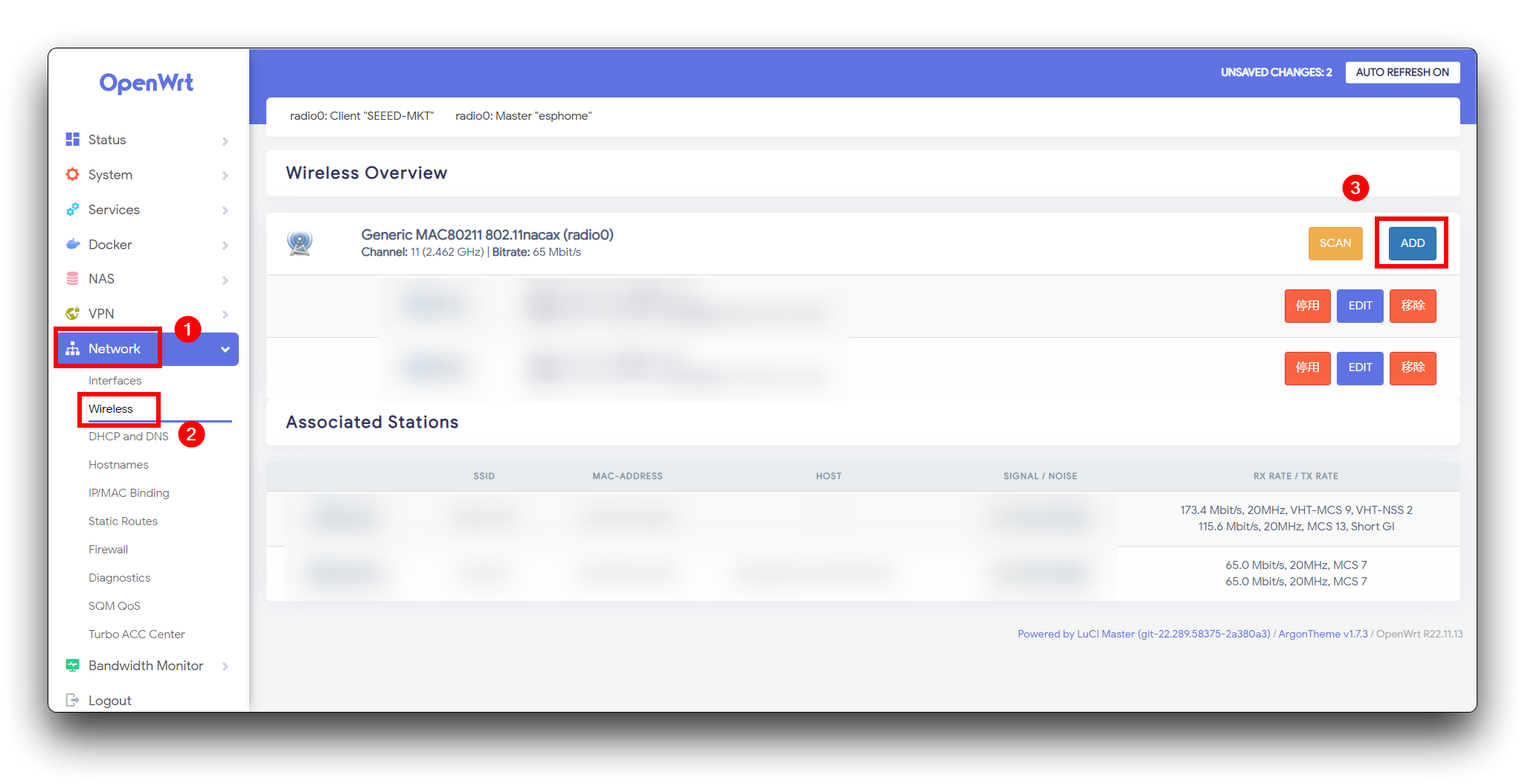
For Transmit Power in Device Configuration, select auto.
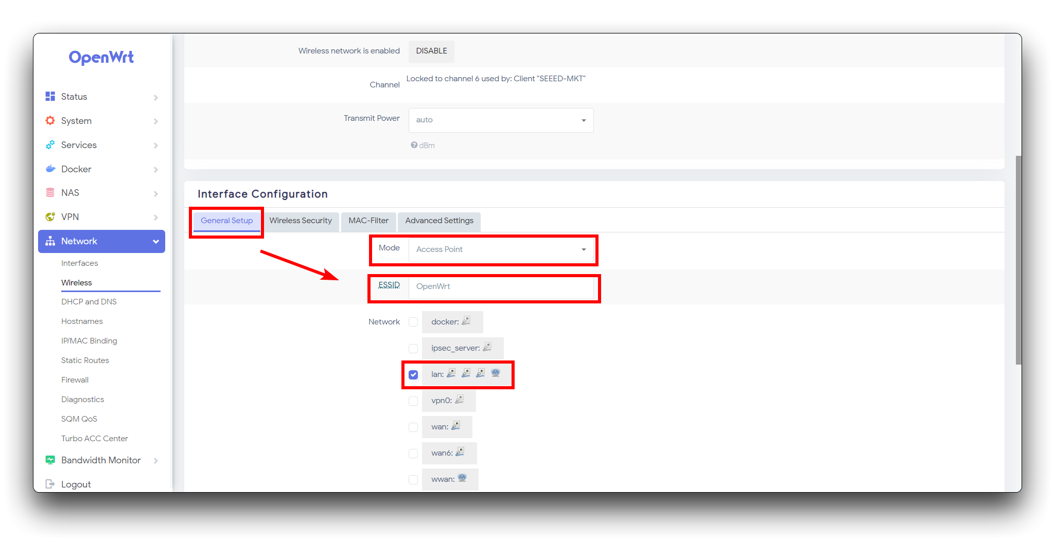
For the Interface Configuration settings, please fill in the following instructions.
- General Setup
- Mode: Depends on how LinkStar accesses the internet. If you are using a cable connection then select Client, if you are connected to WiFi then select Access Point.
- ESSID: Enter the name of your WiFi, please try not to have spaces or special characters.
- Network: check lan.
- Wireless Security
- Encryption: WPA2-PSK
- Key: Enter the WiFi password you wish to set.
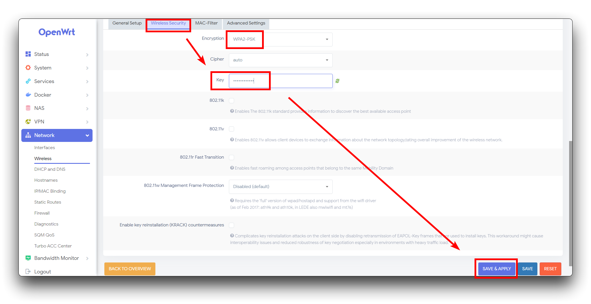
Once you have filled in the above information, click Save and Apply in the bottom right hand corner and wait a few moments for LinkStar to open a hotspot.
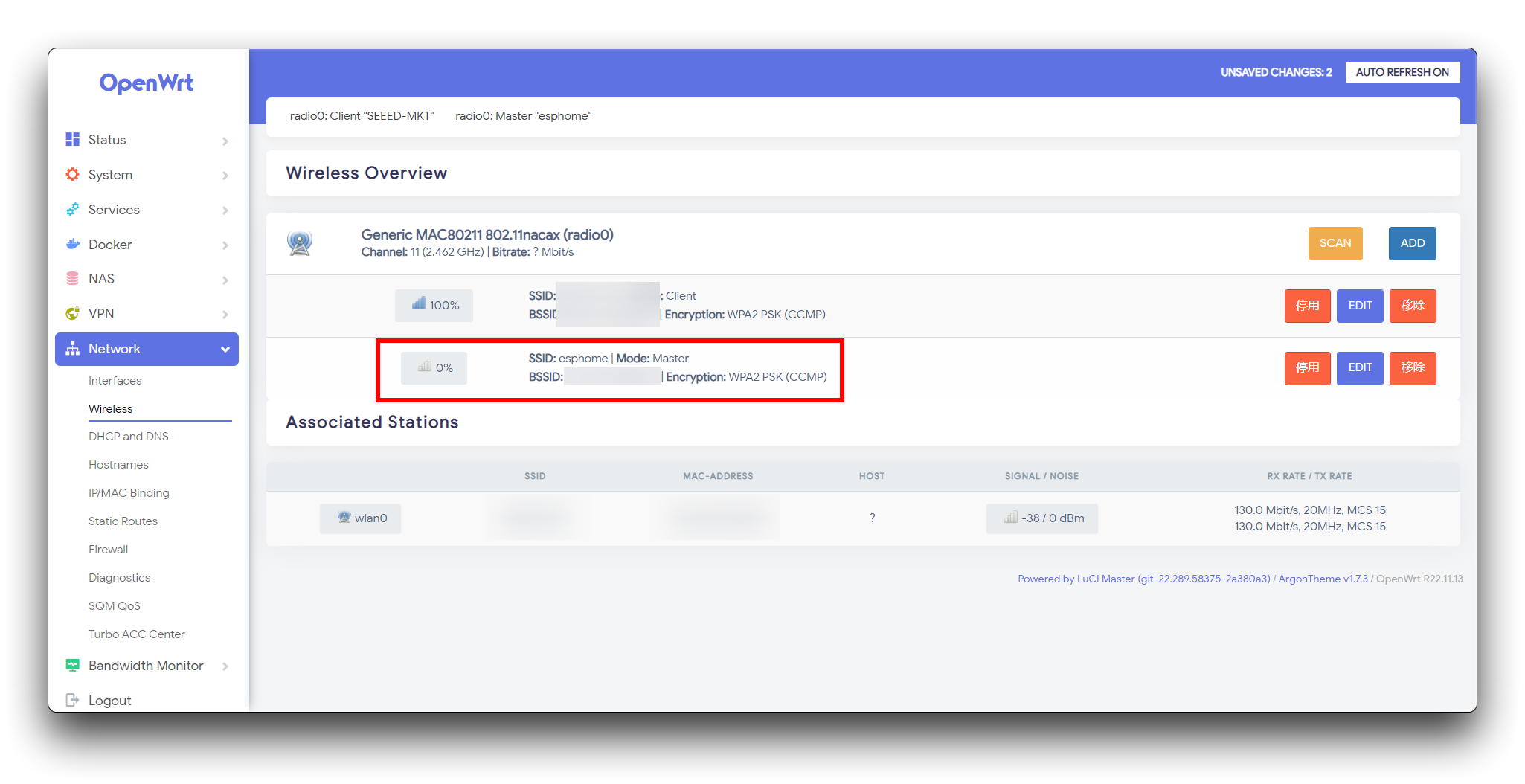
When no device is connected to this hotspot, it will be displayed as no signal.
All things considered, let's return to the Home Assistant page.
Click on the NEW DEVICE. Then click on Continue.
Under the new pop-up window, please enter the name of the application you wish to set up, as well as the name and password of the hotspot you have set up in LinkStar (Or your own WiFi). Make sure that the XIAO ESP32C3 and Home Assistant on the same LAN.
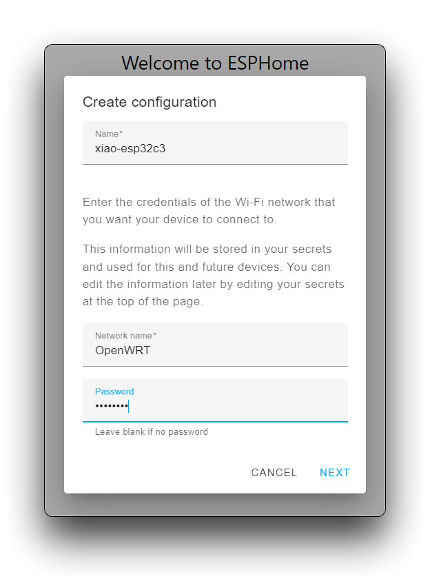
Then click Next.
In the device type, please select ESP32-C3.
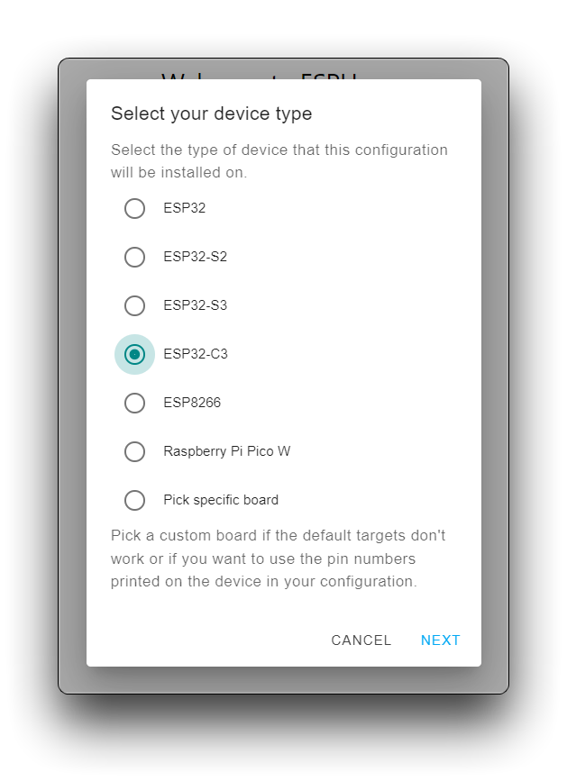
Then click Next.
Click on the Encryption key and save it in a secure location, we will use this key in a later step.
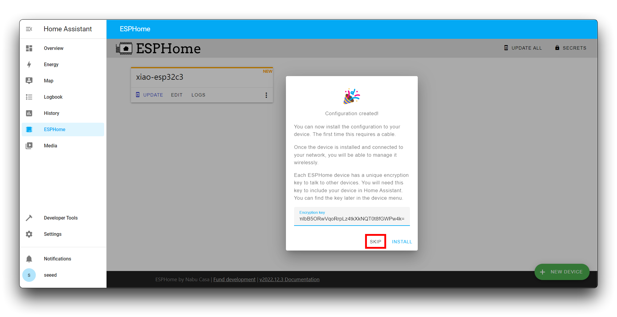
Then click SKIP.
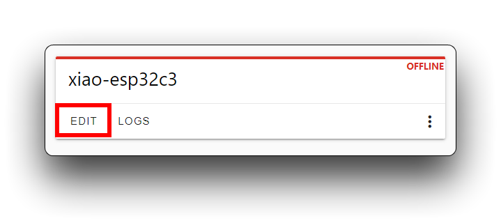
Then, we click on the device tab we just created, with the EDIT button in the bottom left corner.
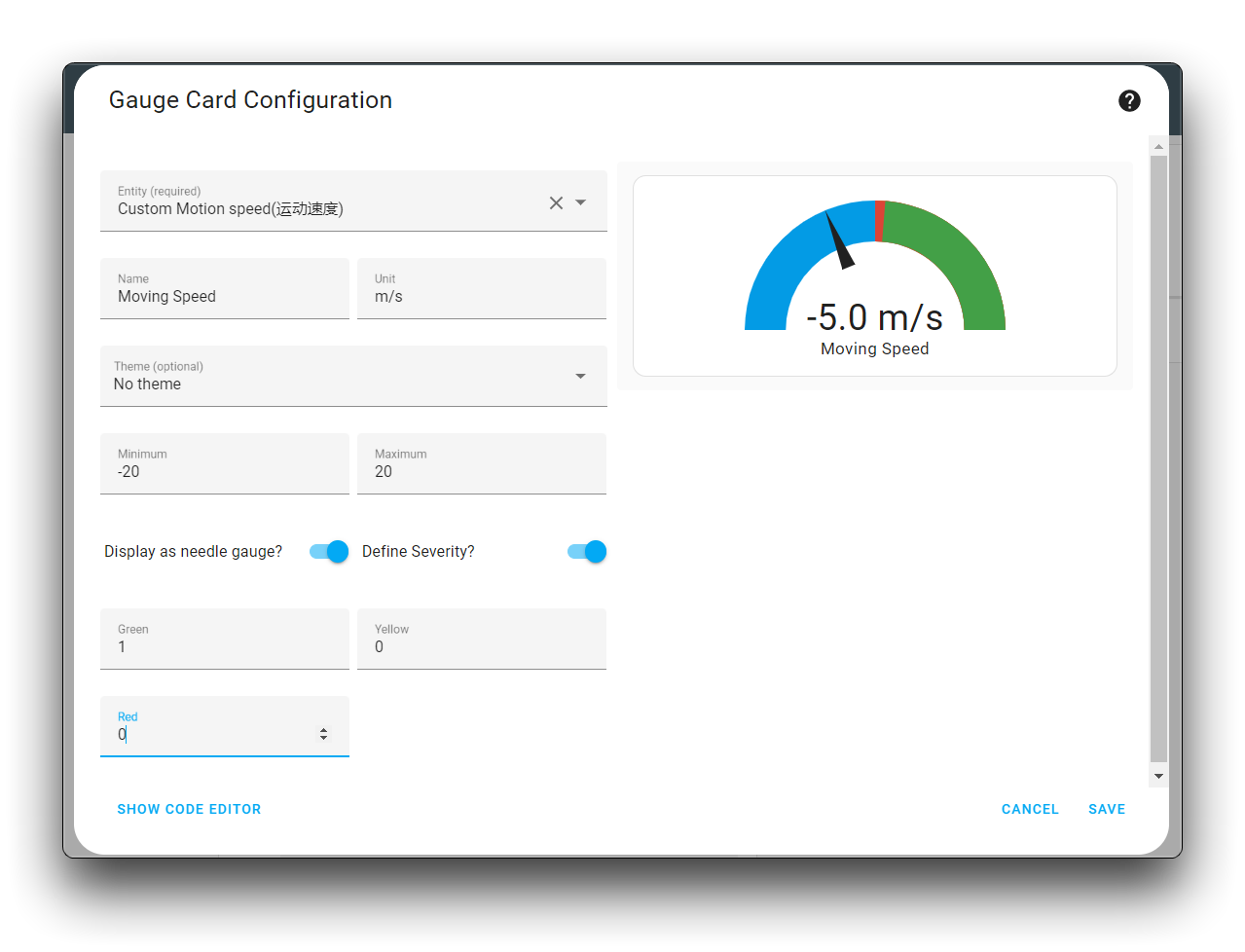
Please note that we need to make changes to this yaml file. We have divided the content to be modified into two main parts, corresponding to one and two in the diagram below.
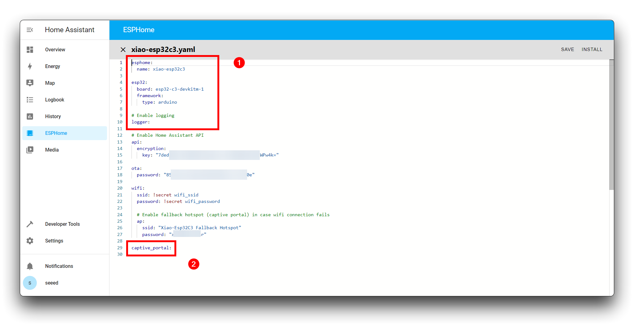
- In the ① of the content, please do not change the device name except the one you have configured, please refer to the code below for the rest of the content.
# part 1:
esphome:
  name: <your device name>    //Please note that your device name is retained here
  platformio_options:
    board_build.flash_mode: dio
    board_build.mcu: esp32c3
  includes:
  - R24dvd_new.h

esp32:
  board: esp32-c3-devkitm-1
  variant: esp32c3
  framework:
    type: esp-idf

# Enable logging
logger:
  hardware_uart: USB_SERIAL_JTAG
  level: DEBUG
- In the ② of the content, delete the words "captive_portal:" and replace with the following.
Click here to preview the full code
uart:
  id: uart_bus
  baud_rate:  115200
  rx_pin: 5
  tx_pin: 4

select:
  - platform: template
    name: "Standard Scene mode"
    id: scene_mode
    icon: mdi:hoop-house
    optimistic: true
    options:
      - "Living room"
      - "Area detection"
      - "Washroom"
      - "Bedroom"
    initial_option: "Living room"
    set_action:
      - logger.log:
            format: "set action option: %s"
            args: ["x.c_str()"]
      - uart.write: !lambda
                  auto index = id(scene_mode).index_of(x);
                  uint8_t value = (uint8_t)index.value() + 1;
                  uint8_t crc = value + 0xB9;
                  return {0x53,0x59,0x05,0x07,0x00,0x01,value,crc,0x54,0x43};

  - platform: template
    name: "Standard unmanned time"
    id: unmanned_time
    icon: mdi:timeline-clock
    optimistic: true
    options:
      - "None"
      - "10s"
      - "30s"
      - "1min"
      - "2min"
      - "5min"
      - "10min"
      - "30min"
      - "1hour"
    initial_option: "None"
    set_action:
      - logger.log:
            format: "Chosen option: %s"
            args: ["x.c_str()"]
      - uart.write: !lambda
                  auto index = id(unmanned_time).index_of(x);
                  uint8_t value = (uint8_t)index.value();
                  uint8_t crc = value + 0x37;
                  return {0x53,0x59,0x80,0x0a,0x00,0x01,value,crc,0x54,0x43};

  - platform: template
    name: "Custom Presence of perception boundary"
    id: custom_presence_of_perception_boundary
    optimistic: true
    options:
      - "0.5m"
      - "1.0m"
      - "1.5m"
      - "2.0m"
      - "2.5m"
      - "3.0m"
      - "3.5m"
      - "4.0m"
      - "4.5m"
      - "5.0m"
    set_action:
      - logger.log:
            format: "Chosen option: %s"
            args: ["x.c_str()"]
      - uart.write: !lambda
                  auto index = id(unmanned_time).index_of(x);
                  uint8_t value = (uint8_t)index.value() + 1;
                  uint8_t crc = value + 0xBF;
                  return {0x53,0x59,0x08,0x0a,0x00,0x01,value,crc,0x54,0x43};

  - platform: template
    name: "Custom Motion trigger boundary"
    id: custom_motion_trigger_boundary
    optimistic: true
    options:
      - "0.5m"
      - "1.0m"
      - "1.5m"
      - "2.0m"
      - "2.5m"
      - "3.0m"
      - "3.5m"
      - "4.0m"
      - "4.5m"
      - "5.0m"
    set_action:
      - logger.log:
            format: "Chosen option: %s"
            args: ["x.c_str()"]
      - uart.write: !lambda
                  auto index = id(unmanned_time).index_of(x);
                  uint8_t value = (uint8_t)index.value() + 1;
                  uint8_t crc = value + 0xC0;
                  return {0x53,0x59,0x08,0x0b,0x00,0x01,value,crc,0x54,0x43};

number:
  - platform: template
    id: sensitivity
    name: "Standard sensitivity"
    icon: mdi:archive-check-outline
    min_value: 0
    max_value: 3
    optimistic: false
    step: 1
    update_interval: 2s
    set_action:
      - uart.write: !lambda
                    uint8_t crc = x + 0xBA;
                    return {0x53,0x59,0x05,0x08,0x00,0x01,(uint8_t)x,crc,0x54,0x43};

  - platform: template
    name: "Standard Maximum detectable range of moving target"
    id: moving_target_detection_max_distance
    icon: mdi:map-marker-path
    unit_of_measurement: "cm"
    min_value: 0
    max_value: 65536
    step: 500
    set_action:
      - uart.write: !lambda
                    int h_num = (int)x >> 8;
                    int l_num = (int)x & 0xff;
                    int crc = 0xB6 + h_num + l_num;
                    return {0x53,0x59,0x07,0x01,0x00,0x02,(uint8_t)(h_num),(uint8_t)(l_num),(uint8_t)crc,0x54,0x43};

  - platform: template
    name: "Standard Maximum detectable range of stationary target"
    id: static_target_detection_max_distance
    icon: mdi:map-marker-path
    unit_of_measurement: cm
    min_value: 0
    max_value: 65536
    step: 500
    set_action:
      - uart.write: !lambda
                    int h_num = (int)x >> 8;
                    int l_num = (int)x & 0xff;
                    int crc = 0xB9 + h_num + l_num;
                    return {0x53,0x59,0x07,0x04,0x00,0x02,(uint8_t)(h_num),(uint8_t)(l_num),(uint8_t)crc,0x54,0x43};

  - platform: template
    name: "Custom Judgment threshold exists"
    id: custom_judgment_threshold_exists
    min_value: 0
    max_value: 250
    step: 1
    set_action:
      - uart.write: !lambda
                    int crc = 0xBD + (int)x;
                    return {0x53,0x59,0x08,0x08,0x00,0x01,(uint8_t)x,(uint8_t)crc,0x54,0x43};

  - platform: template
    name: "Custom Motion amplitude trigger threshold"
    id: custom_motion_amplitude_trigger_threshold
    min_value: 0
    max_value: 250
    step: 1
    set_action:
      - uart.write: !lambda
                    int crc = 0xBE + (int)x;
                    return {0x53,0x59,0x08,0x09,0x00,0x01,(uint8_t)x,(uint8_t)crc,0x54,0x43};

  - platform: template
    name: "Custom Mode Settings"
    id: custom_mode_settings
    icon: mdi:cog
    min_value: 0
    max_value: 250
    step: 1
    set_action:
      - uart.write: !lambda
                    int crc = 0xBB + (int)x;
                    return {0x53,0x59,0x05,0x09,0x00,0x01,(uint8_t)x,(uint8_t)crc,0x54,0x43};

  - platform: template
    name: "Custom Mode Settings End"
    id: custom_mode_setting_completed
    icon: mdi:cog
    min_value: 0
    max_value: 250
    step: 1
    set_action:
      - uart.write: !lambda
                    int crc = 0xBC + (int)x;
                    return {0x53,0x59,0x05,0x0a,0x00,0x01,(uint8_t)x,(uint8_t)crc,0x54,0x43};

  - platform: template
    name: "Custom Custom Mode Query"
    icon: mdi:cog
    id: custom_mode_query
    min_value: 0
    max_value: 250
    step: 1
    set_action:
      - uart.write: !lambda
                    int crc = 0x3B + (int)x;
                    return {0x53,0x59,0x05,0x89,0x00,0x01,(uint8_t)x,(uint8_t)crc,0x54,0x43};

  - platform: template
    name: "Custom Motion trigger time"
    id: custom_motion_trigger_time
    icon: mdi:camera-timer
    unit_of_measurement: "ms"
    min_value: 0
    max_value: 4294967295
    step: 5000
    set_action:
      - uart.write: !lambda
                    int crc = 0xC4 + (int)x;
                    int h24_num = ((int)x >> 24) & 0xff;
                    int h16_num = ((int)x >> 16) & 0xff;
                    int h8_num = ((int)x >> 8) & 0xff;
                    int l8_num = (int)x & 0xff;
                    return {0x53,0x59,0x08,0x0c,0x00,0x04,(uint8_t)h24_num,(uint8_t)h16_num,(uint8_t)h8_num,(uint8_t)l8_num,(uint8_t)crc,0x54,0x43};

  - platform: template
    name: "Custom Movement to rest time"
    id: custom_movement_to_rest_time
    icon: mdi:camera-timer
    unit_of_measurement: "ms"
    min_value: 0
    max_value: 4294967295
    step: 5000
    set_action:
      - uart.write: !lambda
                    int crc = 0xC5 + (int)x;
                    int h24_num = ((int)x >> 24) & 0xff;
                    int h16_num = ((int)x >> 16) & 0xff;
                    int h8_num = ((int)x >> 8) & 0xff;
                    int l8_num = (int)x & 0xff;
                    return {0x53,0x59,0x08,0x0d,0x00,0x04,(uint8_t)h24_num,(uint8_t)h16_num,(uint8_t)h8_num,(uint8_t)l8_num,(uint8_t)crc,0x54,0x43};

  - platform: template
    name: "Custom Time of entering unmanned state"
    id: custom_time_of_enter_unmanned
    icon: mdi:camera-timer
    unit_of_measurement: "ms"
    min_value: 0
    max_value: 4294967295
    step: 5000
    set_action:
      - uart.write: !lambda
                    int crc = 0xC6 + (int)x;
                    int h24_num = ((int)x >> 24) & 0xff;
                    int h16_num = ((int)x >> 16) & 0xff;
                    int h8_num = ((int)x >> 8) & 0xff;
                    int l8_num = (int)x & 0xff;
                    return {0x53,0x59,0x08,0x0e,0x00,0x04,(uint8_t)h24_num,(uint8_t)h16_num,(uint8_t)h8_num,(uint8_t)l8_num,(uint8_t)crc,0x54,0x43};

text_sensor:
- platform: custom
  lambda: |-
    auto my_custom_sensor = new MyCustomTextSensor();
    App.register_component(my_custom_sensor);
    return {my_custom_sensor->Heartbeat};

  text_sensors:
    - name: "Standard Heartbeat"
      icon: mdi:connection

- platform: template
  name: "Standard Product model"
  id: product_mode
  icon: mdi:information-outline
  on_raw_value:
    then:
      - logger.log: text_sensor on_raw_value

- platform: template
  name: "Standard Product ID"
  id: product_id
  icon: mdi:information-outline

- platform: template
  name: "Standard Hardware model"
  id: hardware_model
  icon: mdi:information-outline

- platform: template
  name: "Standard Firmware version"
  id: firmware_version
  icon: mdi:information-outline

- platform: template
  name: "Standard protocol type"
  id: protocol_type
  icon: mdi:information-outline

- platform: template
  name: "Standard moving direction"
  id: keep_away
  icon: mdi:walk

- platform: template
  name: "Standard Sports information"
  id: motion_status
  icon: mdi:human-greeting

- platform: template
  name: "Standard Presence information"
  id: someoneExists
  icon: "mdi:motion-sensor"

- platform: template
  name: "Custom Presence of detection"
  id: custom_presence_of_detection
  icon: mdi:signal-distance-variant

# - platform: template
#   name: "Custom Motion distance"
#   id: custom_motion_distance

# - platform: template
#   name: "Custom Static distance"
#   id: custom_static_distance

# - platform: template
#   name: "Custom Spatial static value"
#   id: custom_spatial_static_value

# - platform: template
#   name: "Custom Spatial motion value"
#   id: custom_spatial_motion_value

# - platform: template
#   name: "Custom Motion speed"
#   id: custom_motion_speed


button:
  - platform: template
    name: "Standard reset"
    id: "reset"
    icon: mdi:reload
    on_press:
      then:
        - logger.log: Button Pressed
        - uart.write: [0x53,0x59,0x01,0x02,0x00,0x01,0x0F,0xBF,0x54,0x43]

switch:
  - platform: template
    id: output_info_switch
    name: "Custom Infor output switch"
    icon: mdi:electric-switch
    assumed_state: true
    turn_on_action:
      - uart.write: [0x53,0x59,0x08,0x00,0x00,0x01,0x01,0xB6,0x54,0x43]
      - delay: 1s
      - lambda: !lambda |-
          id(product_mode).publish_state("");
          id(product_id).publish_state("");
          id(hardware_model).publish_state("");
          id(firmware_version).publish_state("");
          id(protocol_type).publish_state("");
    turn_off_action:
      - uart.write: [0x53,0x59,0x08,0x00,0x00,0x01,0x00,0xB5,0x54,0x43]

sensor:
- platform: custom
  lambda: |-
    auto my_custom_sensor = new UartReadLineSensor(id(uart_bus));
    App.register_component(my_custom_sensor);
    return {
      my_custom_sensor->movementSigns,
      my_custom_sensor->inited,
    };
  sensors:
    - name: "Standard body movement"
      id: movementSigns
      icon: "mdi:human-greeting-variant"
      device_class: "temperature"
      state_class: "measurement"

    - name: "Standard inited"
      id: inited
      icon: mdi:all-inclusive

- platform: template
  name: "Custom Motion distance"
  id: custom_motion_distance
  icon: mdi:signal-distance-variant
  on_value:
    then:
      # - logger.log: Custom Motion distance on_value
      - logger.log:
            format: "Custom Motion distance on_value : %d"
            args: ["x"]
  on_raw_value:
    then:
      - logger.log:
            format: "Custom Motion distance on_raw_value : %d"
            args: ["x"]


- platform: template
  name: "Custom Static distance"
  id: custom_static_distance
  icon: mdi:signal-distance-variant

- platform: template
  name: "Custom Spatial static value"
  id: custom_spatial_static_value
  icon: mdi:counter

- platform: template
  name: "Custom Spatial motion value"
  id: custom_spatial_motion_value
  icon: mdi:counter

- platform: template
  name: "Custom Motion speed"
  id: custom_motion_speed
  icon: mdi:run-fast
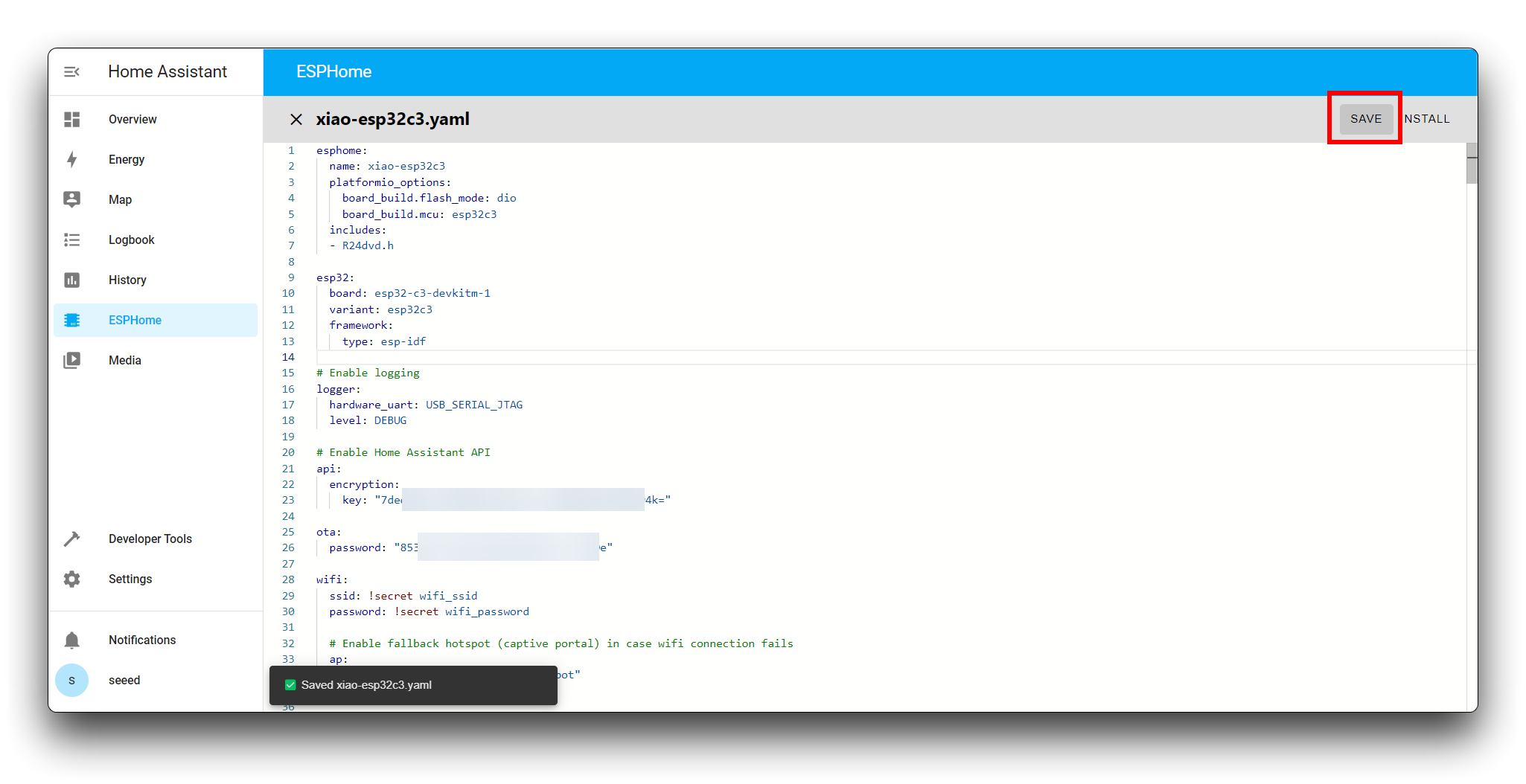
Then, please click on the Save button in the top right corner.
- Method 1: Compile and upload directly
If you are using an x86 device and can see XIAO on the device port, then you can compile and upload the program to XIAO.
Connect XIAO to your device.
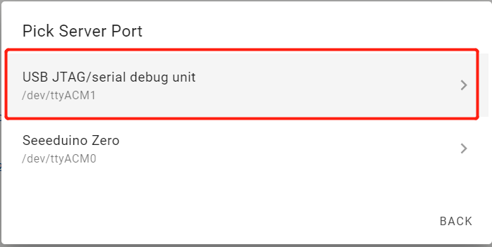
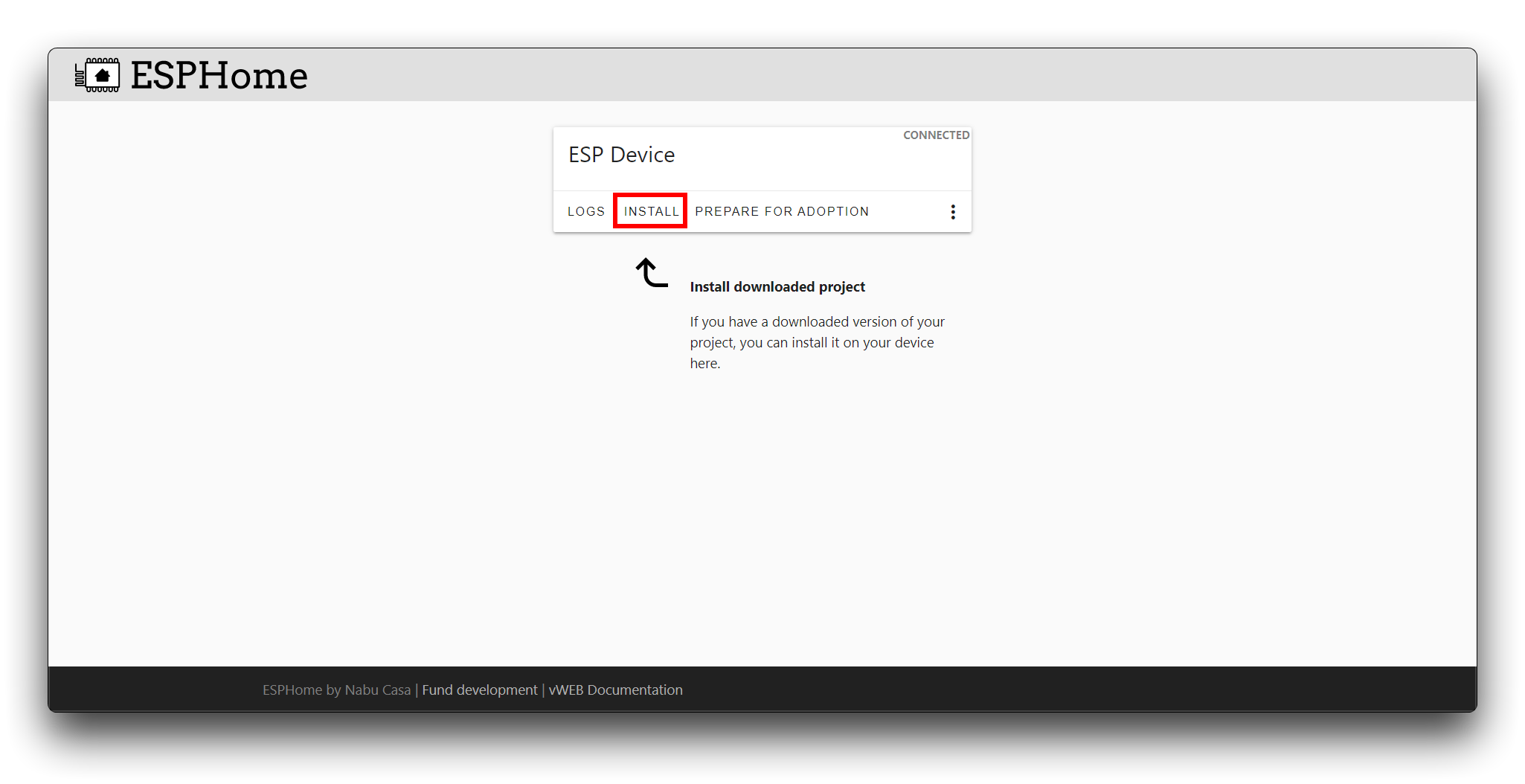
Click on the three dots in the bottom right corner of the device bar and select Install.
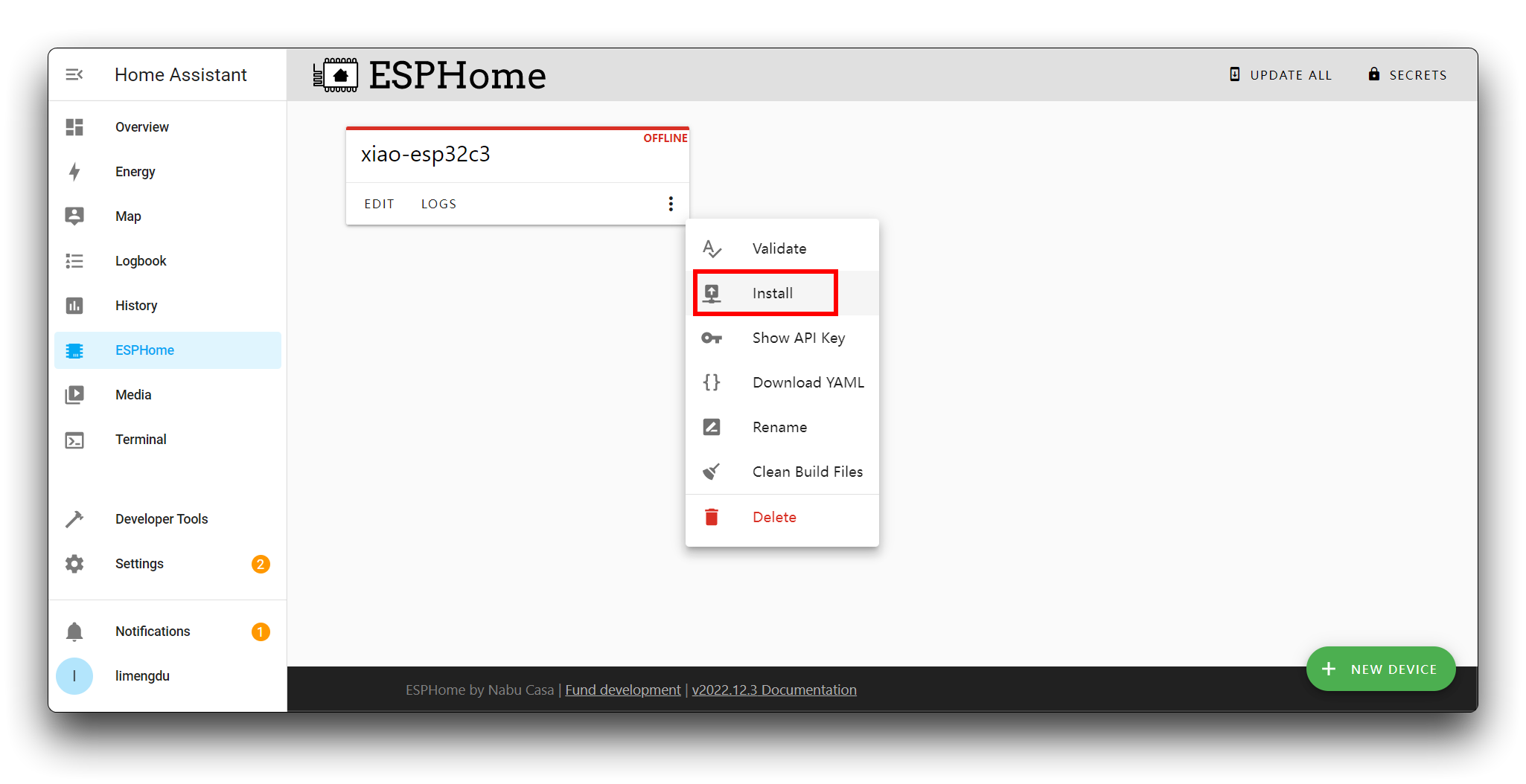
Click Plug into the computer running ESPHome Dashboard.
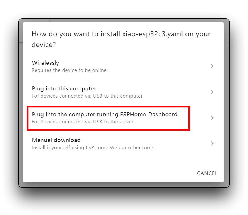
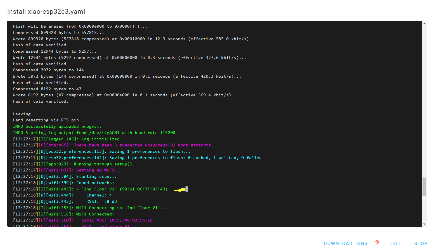
Select the connected port.
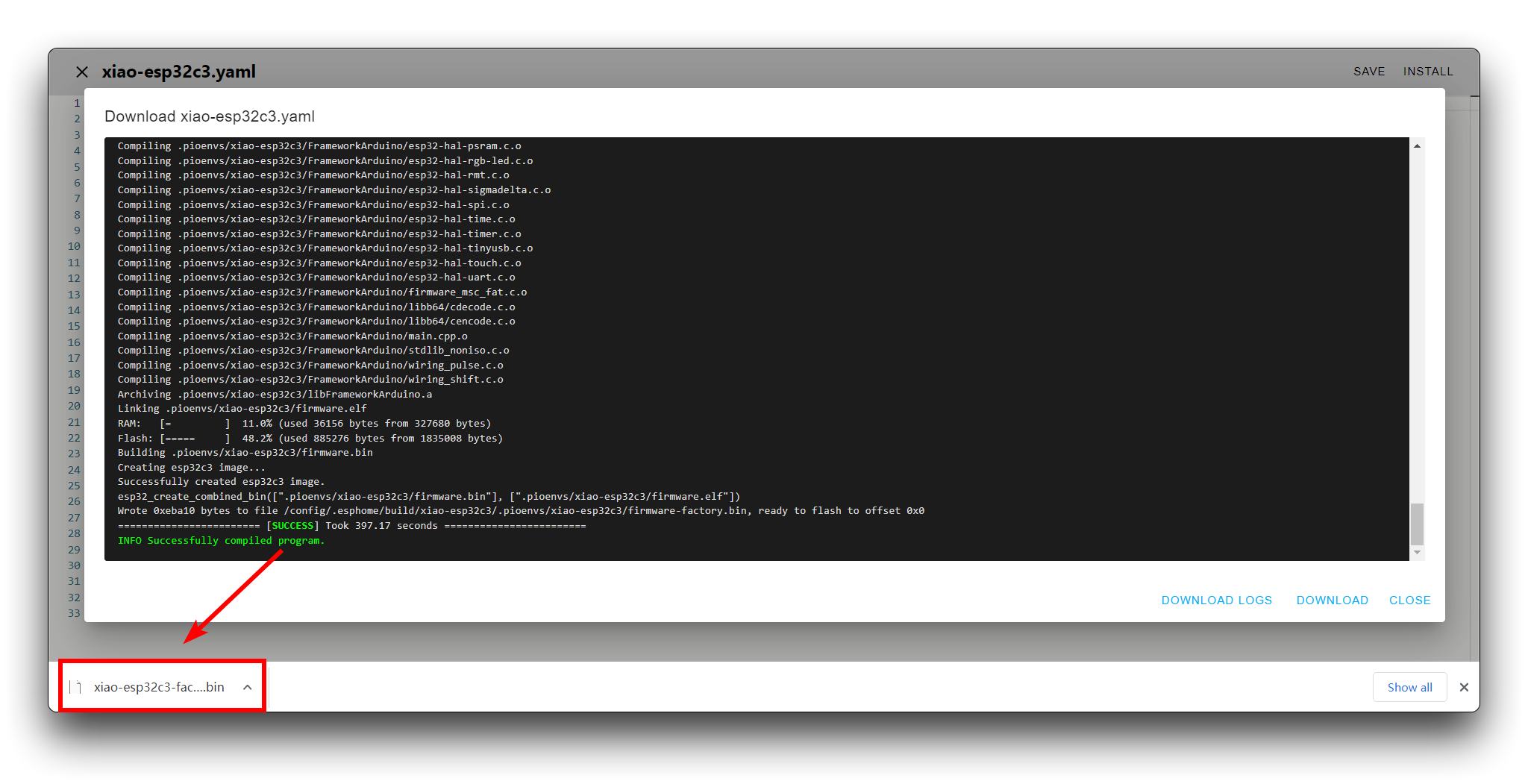
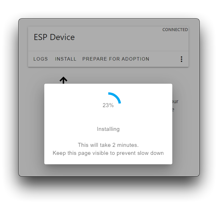
Now it will download all the necessary board packages and flash the ESPHome firmware into the XIAO ESP32C3. If the flashing is successful, you will see the following output.
If you are unable to find the port after connecting XIAO to your device, then you can try using the second method.
- Method 2: Upload compiled firmware using the host
Soft routes like LinkStar H68K do not support recognition of external MCU devices, we need to download the compiled firmware first and then upload the firmware via another PC.
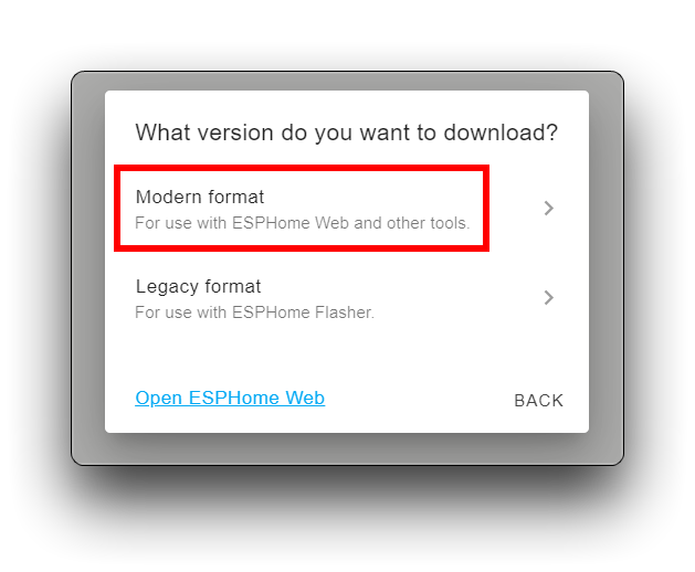
Click on the Install button in the top right hand corner. Then select the last item Manual download.

Select Modern format.
It will then take a long time to download and compile, so please be patient. Once everything is ready, the firmware will be automatically downloaded to your computer.
To upload the firmware to XIAO ESP32C3 there are couple options here we show 2 ways of doing it:
- Option 1: using the ESPhome Web tool to upload.
Make sure you have the right drivers installed. Below are the drivers for common chips used in ESP devices.
-
CP2102 drivers: Windows & Mac
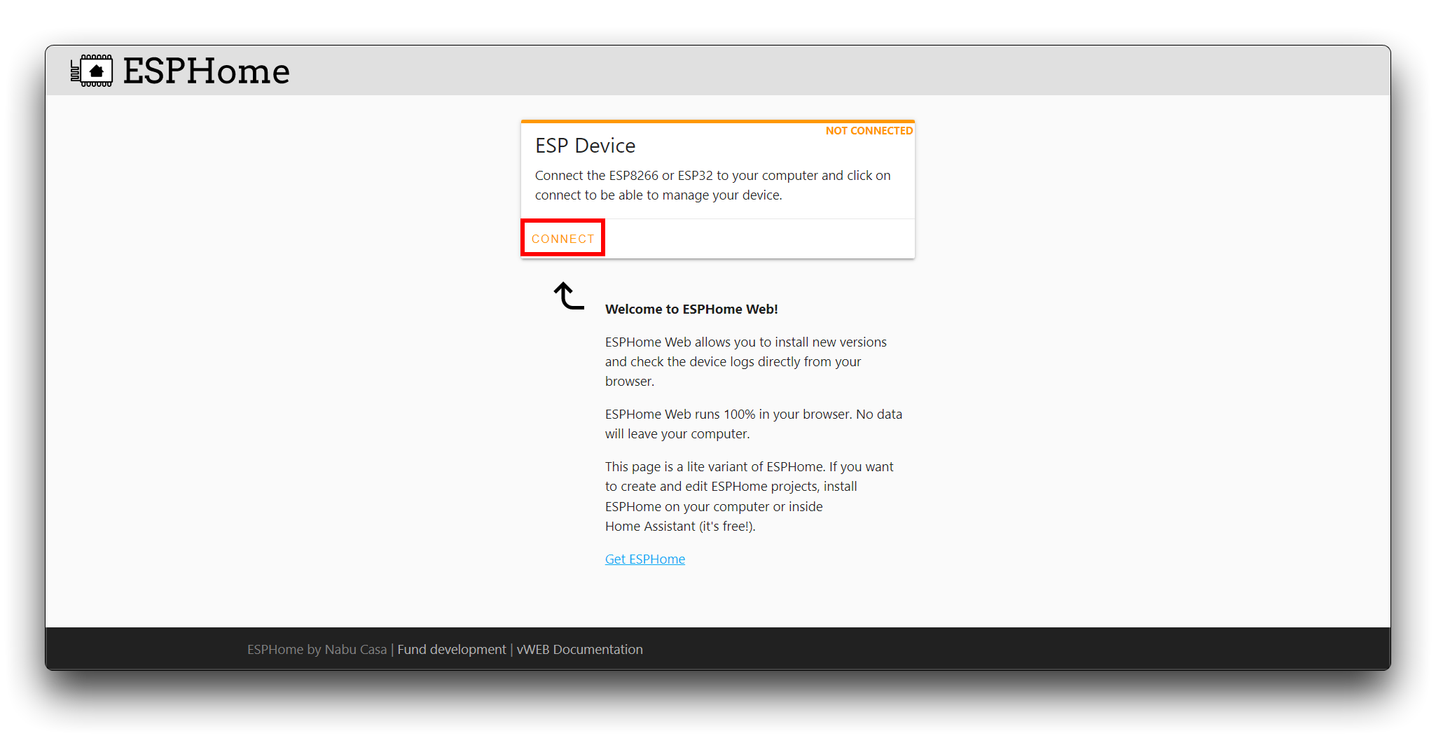
Open the ESPhome Web tool with Chrome or Edge web browser.
Click CONNECT.
select the XIAO ESP32 serial port in the popup window.
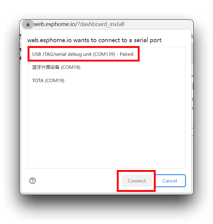
Click INSTALL and then select the .bin file downloaded from above steps.
- Option 2: Using the esphome-flasher tool.
If you are still unable to upload firmware using method one after installing the driver and changing browsers, then you can try using method two. Please refer to the official tutorial for specific installation methods and instructions.
:::tip If you wish to observe the log messages of the XIAO ESP32C3, you can also view them through the View Logs button of this software.

Once the upload is complete, you can disconnect the XIAO ESP32C3 from the PC (unless you have a need to view the logs) and simply power the XIAO separately.
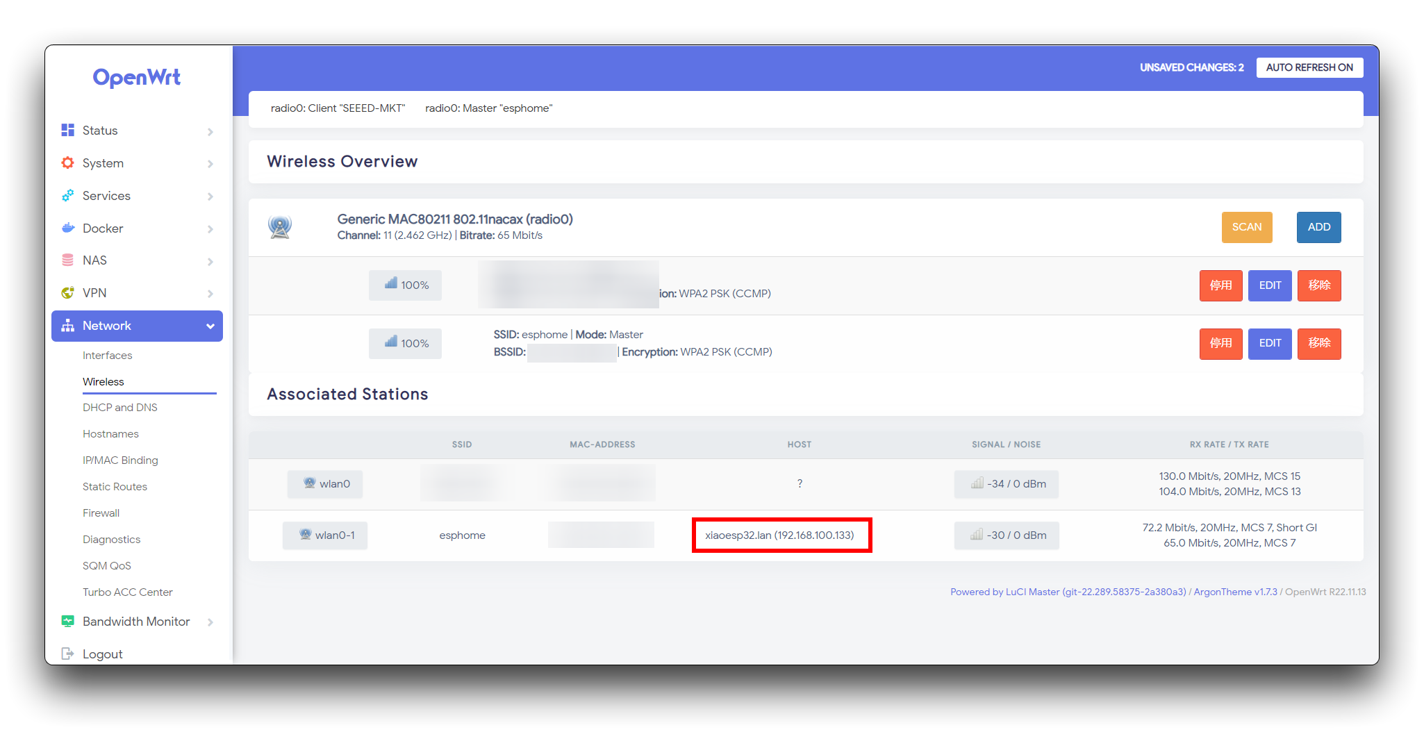
If all goes well, the XIAO ESP32C3 will search for and connect to the WiFi you have set up for it.
Just like me, I use LinkStar H68K's network. You can find it in the network options and see the IP address assigned to it by LinkStar H68K.
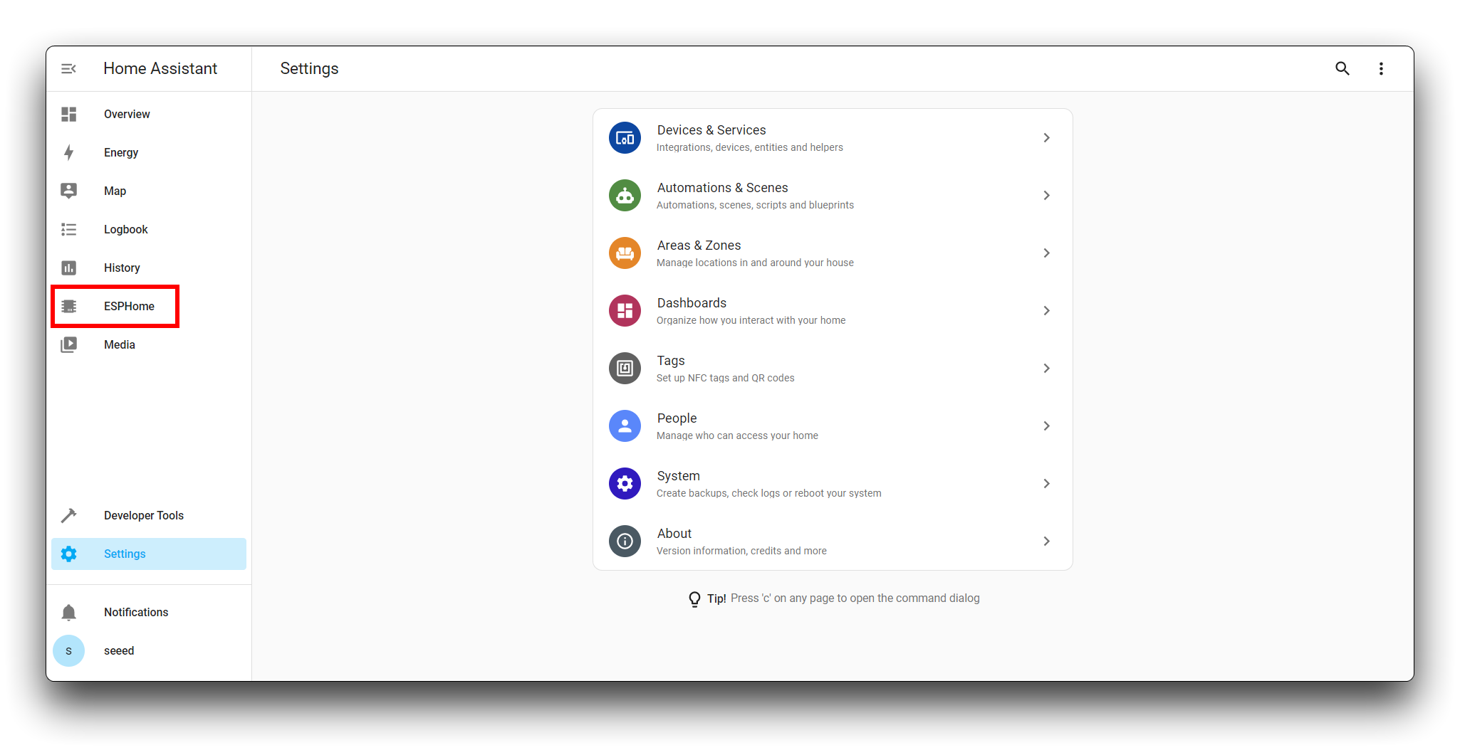
Normally, at this point in Home Assistant, the status of the device will also change from offline to online.
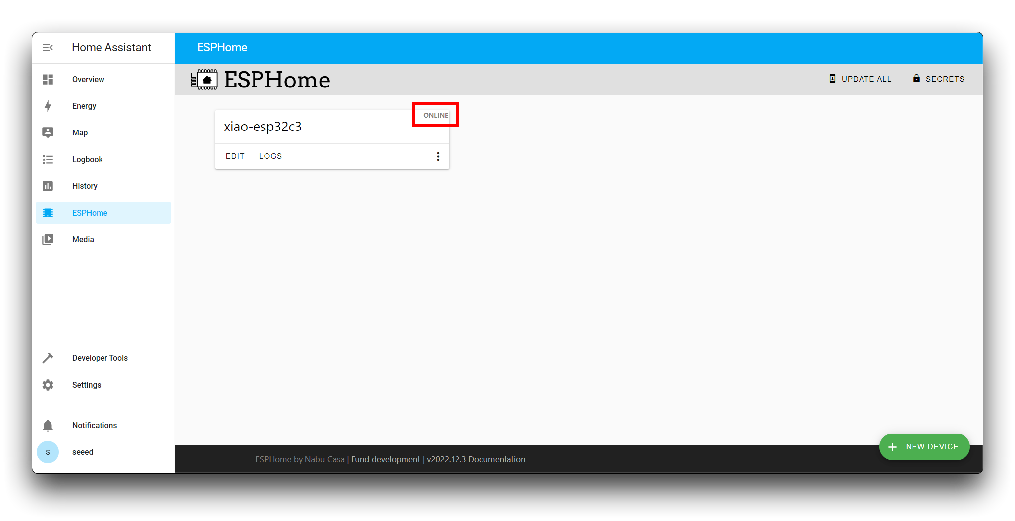
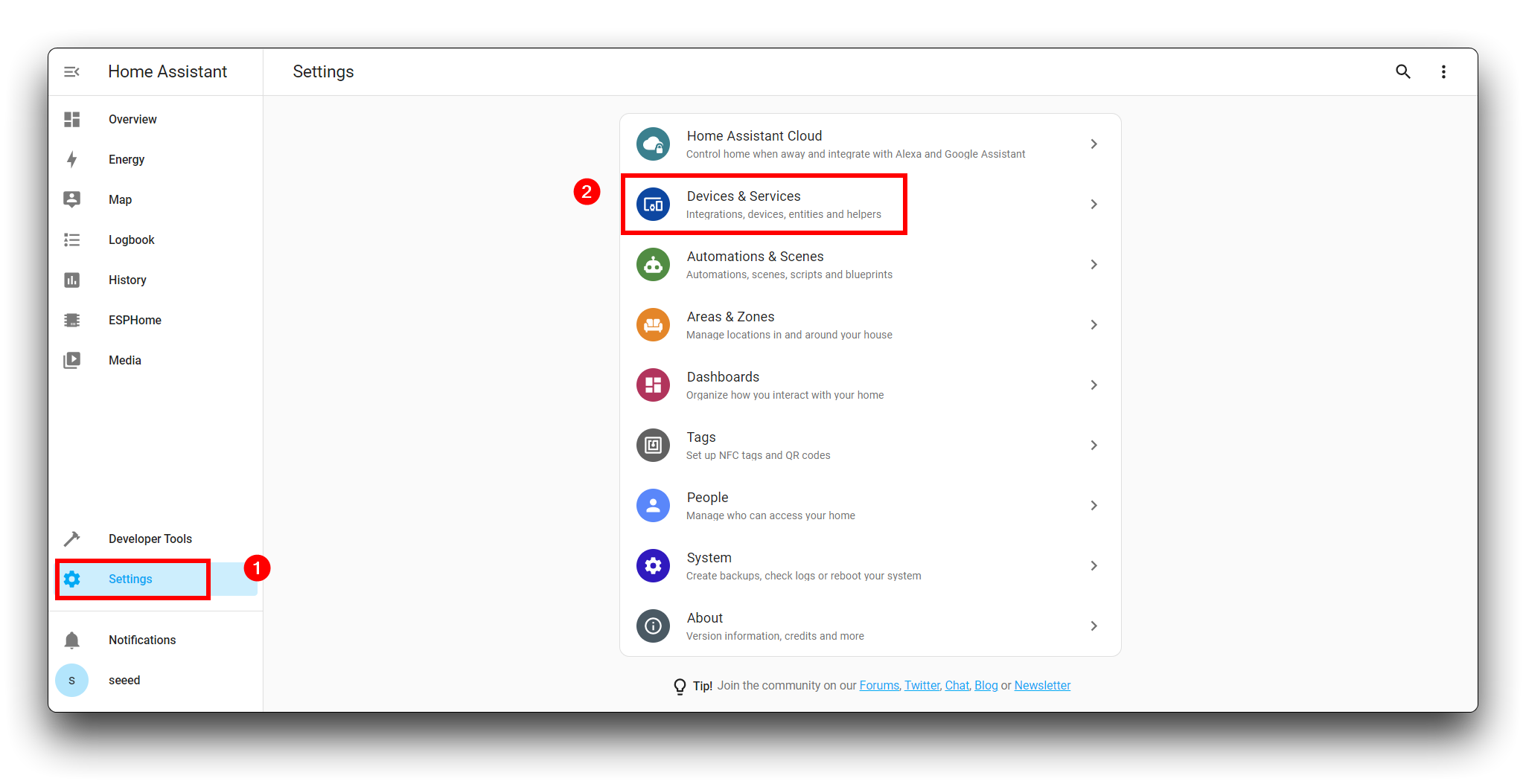
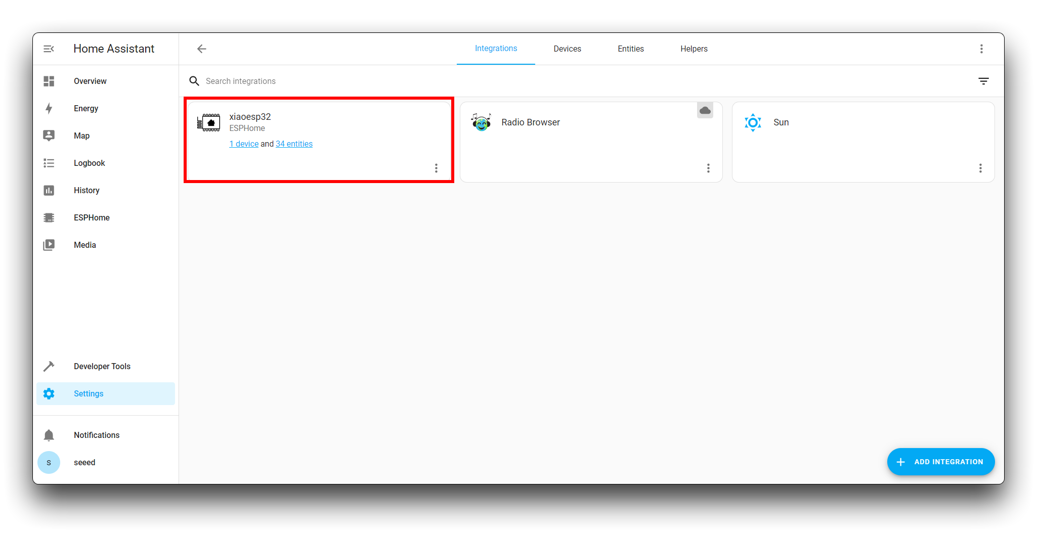
If you do not have many Home Assistant devices on your LAN, Home Assistant can automatically search for and add your ESP devices to the Devices tab. You can see this device inside the Devices & Services tab in Settings.
If it does not automatically search, you can also connect to the XIAO ESP32C3 based on its IP address.
Click ADD INTEGRSTION and search for esphome.
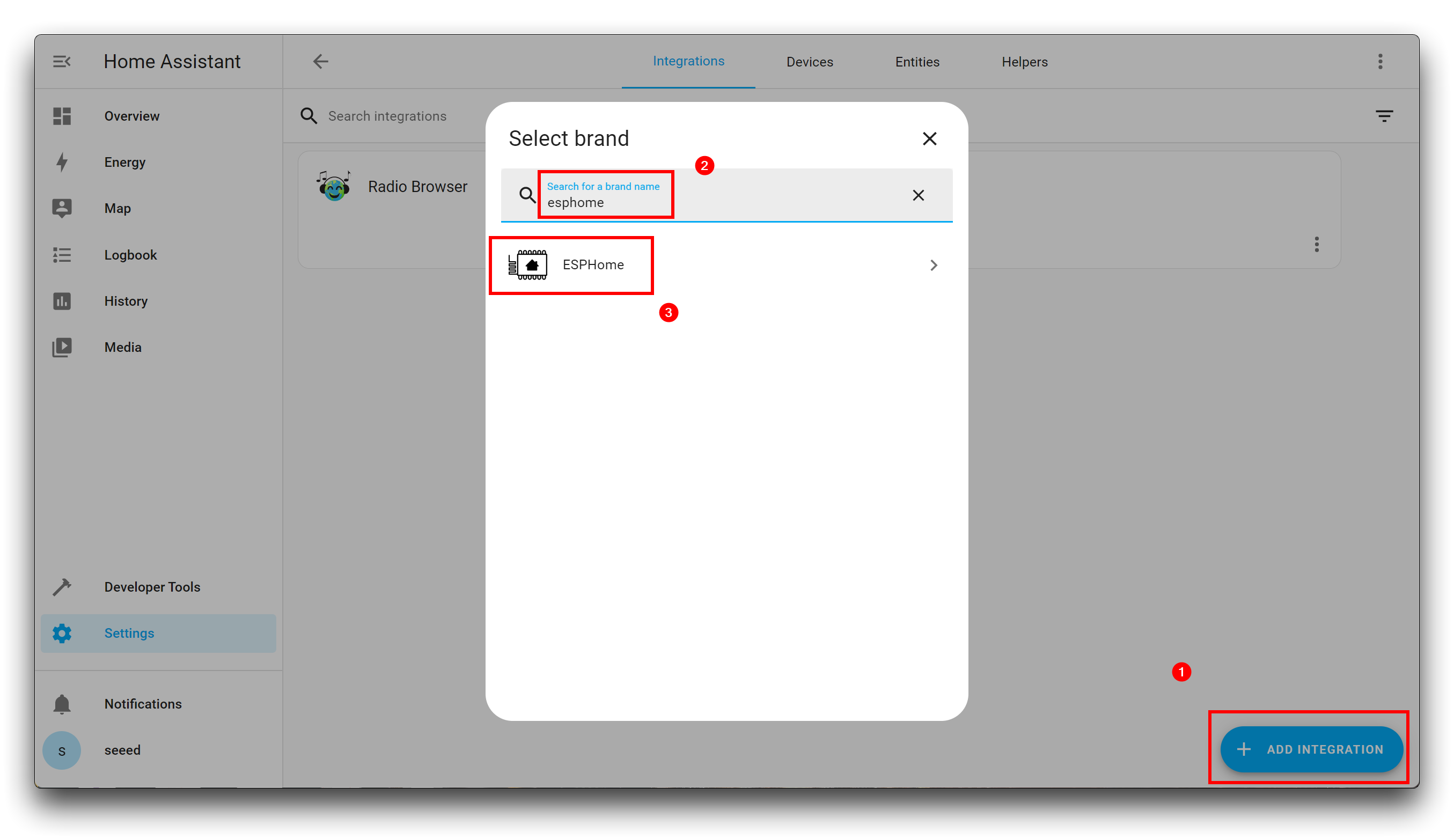
Then enter the IP address of the XIAO ESP32C3 with port number 6053. Then click on SUBMIT.
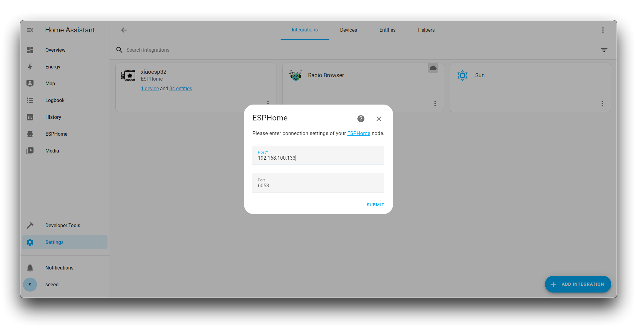
If the IP address and port number entered are correct, then you will see that you are asked to enter the Encryption key, which we asked to save in step 4.
Then click on SUBMIT.
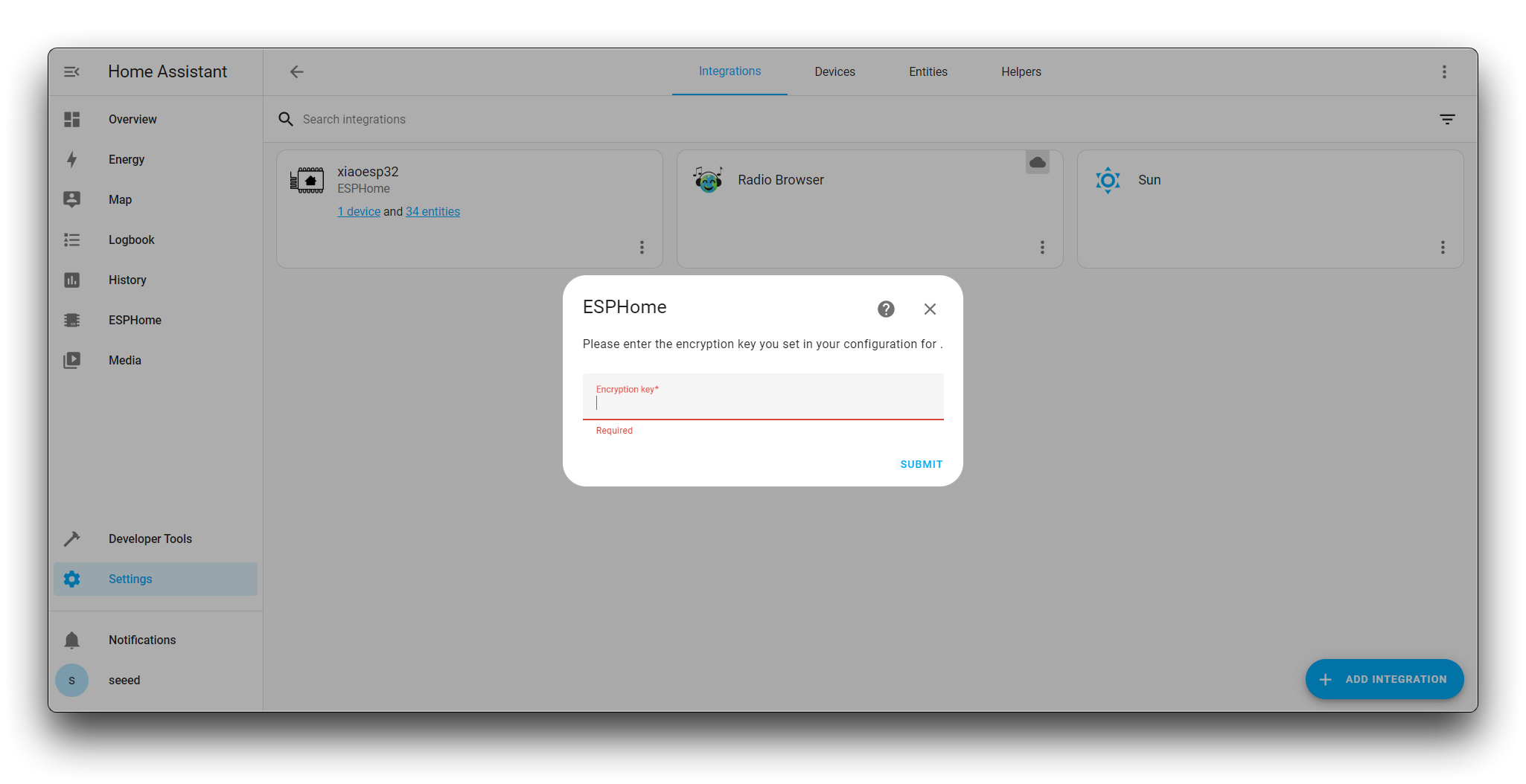
At this point, the steps to add the device have been successfully completed.
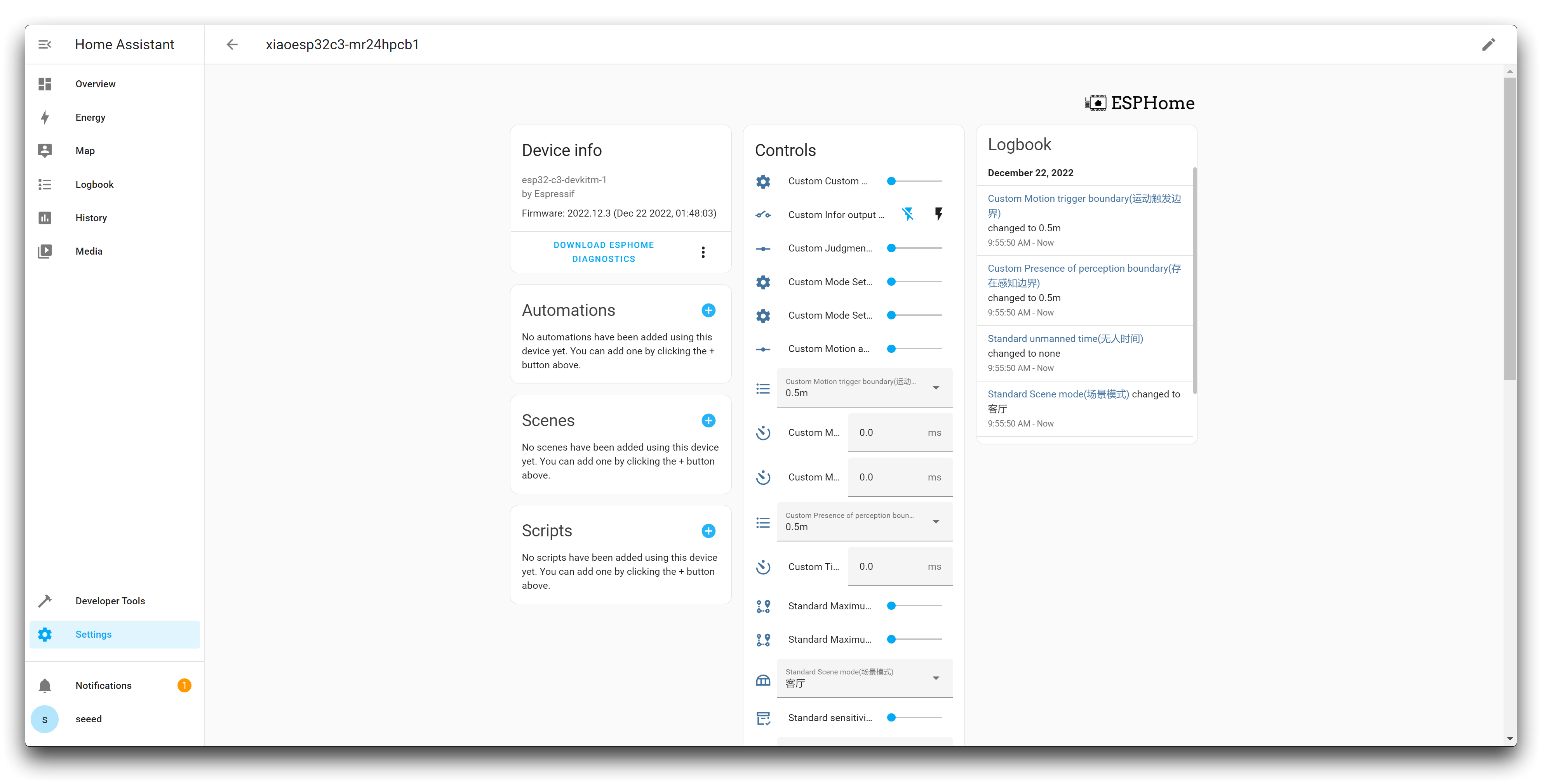
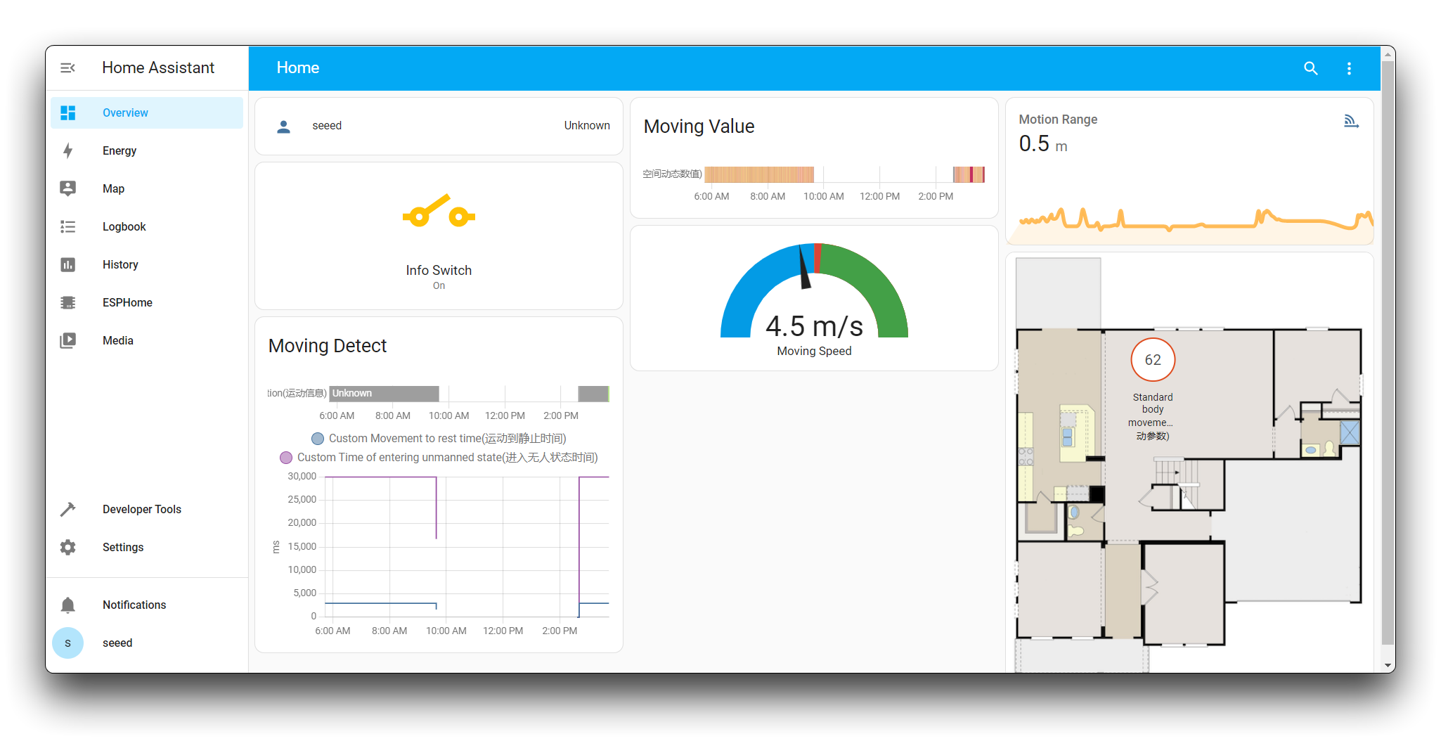
We come to the Home Assistant's overview tab. We give a general overview of the basic functions of the operating panel.
Firstly, there is the Custom Infor output switch. The icon on the left indicates that the information output is switched off, while the icon on the right indicates that the information output is switched on. If you want to see the sensor return information in real time, then you should have to click on the lightning bolt icon on the right.

At the bottom of the card is a real-time data display page. Here you can observe the millimetre wave changes within the monitored environment and adjust the parameters in the card according to your location.

Due to space limitations, you can refer to the following two documents for more information on the use of the sensor and a more detailed explanation of the parameters.
- 24GHz mmWave Human Static Presence Module Lite Wiki
- 24GHz mmWave Human Static Presence Module Lite User Manual
- 24GHz mmWave Human Static Presence Module Lite sensor Datasheet
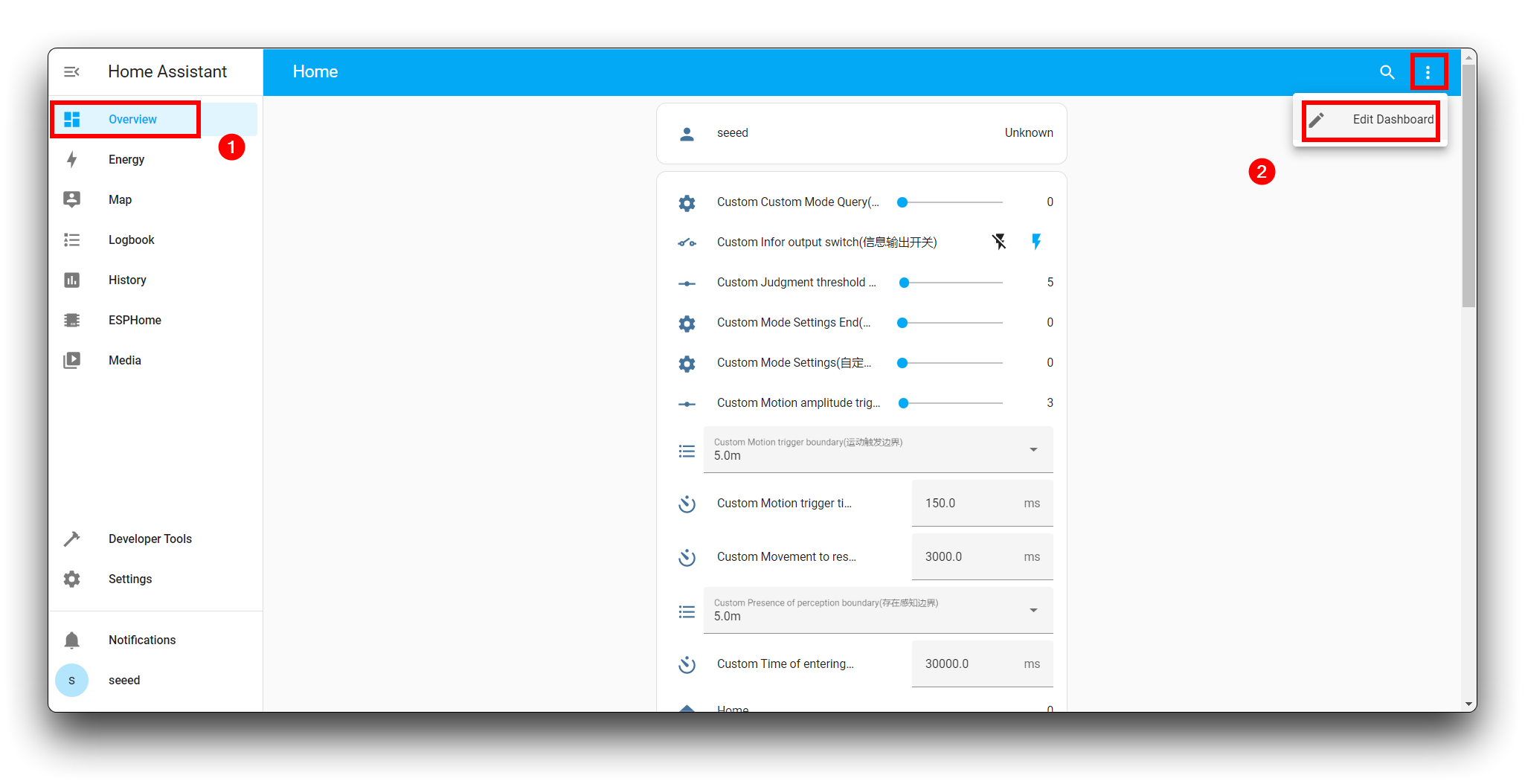
If you find the default cards very boring and unfriendly for presenting data, Home Assistant offers a wide range of ready-made dashboards to choose from.
You can make your own dashboard to suit your preferences.
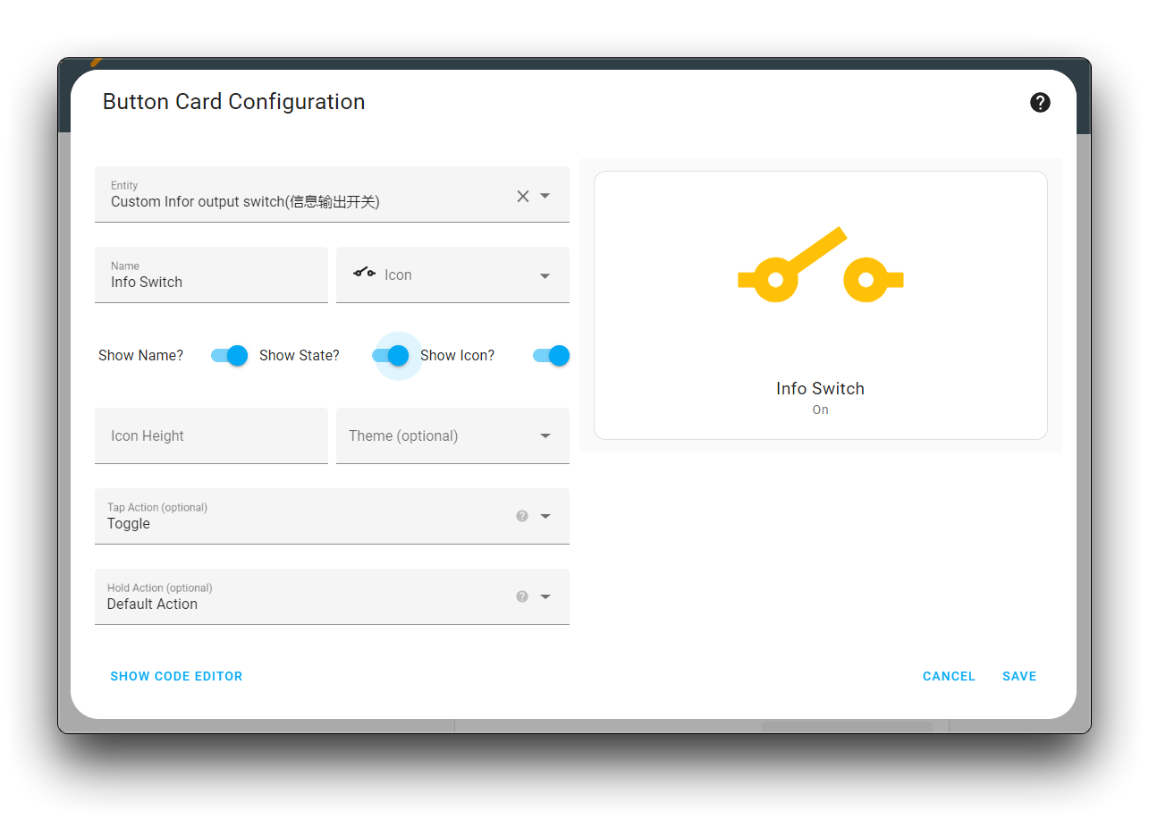
For example, the option to control the output of information is turned into a nice switch.
Turning the speed of human movement into a visual dashboard display.
This is what I came up with. It looks like it has the makings of a smart home control centre.
So far, we have successfully concluded our tutorial content.
Of course, there is more to the XIAO ESP32C3 than just support for the 24GHz mmWave Human Static Presence Module Lite in Home Assistant, and you can find more tutorials for your own use in this document.
Get your creative juices flowing!
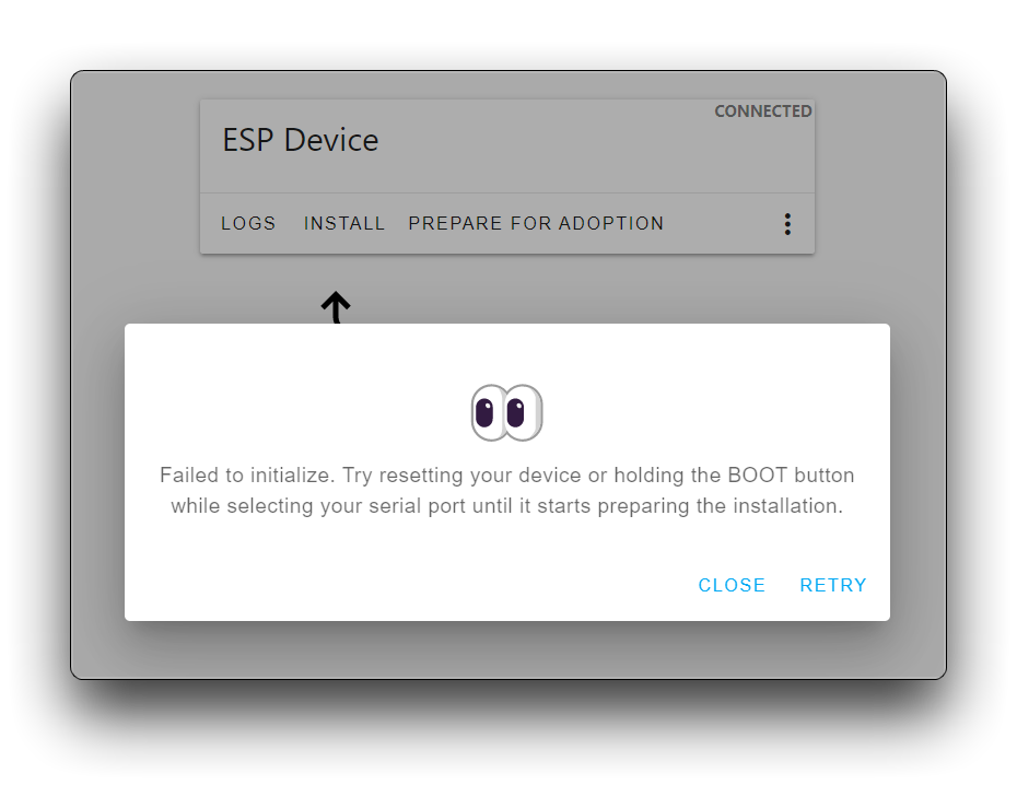
A: If this prompt appears while uploading, disconnect the XIAO ESP32C3 from the PC. Then, hold the BOOT BUTTON, connect the board to your PC while holding the BOOT button, and then release it to enter bootloader mode. At this point it is sufficient to reconnect and upload the firmware again.
A: When executing the following commands, you need to select your system version, otherwise an error will occur. For example, my computer is Ubuntu 22.04, then the command that should be executed is as follows.
sudo apt install python3

pip3 install -U \
    -f https://extras.wxpython.org/wxPython4/extras/linux/gtk3/ubuntu-22.04/ \
    wxPython

pip3 install esphomeflasher
FAQ3: I filled in the correct WiFi and password, why don't I see the IP address of the XIAO ESP32C3?
A: When you encounter this problem, please check that the XIAO ESP32C3's antenna is connected in place. If the antenna is already connected, please make sure that the XIAO is not further than 3m from the LinkStar if possible (unless you have replaced the antenna with a more powerful one). If you still do not see XIAO, you can use the esphome flasher software to check the XIAO log information and check the XIAO connection through the logs. You can re-plug the xiao to let it try to search for WiFi and connect again.
:::caution As of June 1, 2023 troubleshooting has revealed that if you set any value or change any scene in the dashboard of ESPHome, there is a possibility that the radar will go down.
As of 31 July 2023, the previous issue that would cause the radar to completely die has now been fixed, so please update the library files and configurator for this tutorial species to work properly. :::
A: In the previous Wiki content, we used the default UART pins (D6, D7) to receive and send data from the radar, but many users feedback there is a need to re-power the radar before it can work. In response, we updated the Wiki content and procedures to replace the serial ports of the radar with D2 and D3, and after testing, this fixes the problem very well.
If you haven't noticed the Wiki update, I suggest you re-wire the radar and re-write the compile and upload process following steps 2 and 5 of this article's tutorial.
However, some users have responded that they still can't get the radar to work properly even after replacing the serial pins. So here, we propose the following methods and steps to check where the problem occurs, if you still can't solve the problem of radar working, please provide your operation steps to the technical support email, which can speed up the processing of after-sales problems.
Please check the following Exclusion in order.
Exclusion 1: Make sure the XIAO ESP32C3 is under the same LAN as the ESPHome deployed device.
If the XIAO ESP32C3 is not under the same LAN as the device of ESPHome, the log you see in Home Assistant is incomplete and cannot be used as the basis of data collection. So please double check your router to see if the IP address of XIAO appears.
Exclusion 2: Check that the Data Live Transfer button is on.
After XIAO is on the network and the device is successfully added, you will be able to see the radar components in the dashboard. Please note that by default the live data transfer button is off, you need to turn it on to be able to see the radar data being reported continuously.
Exclusion 3: Check whether the radar can work properly.
We need to make sure that the radar works well with the XIAO ESP32C3 first, which will allow us to quickly identify whether it is a problem with ESPHome or the product. Please upload the following code to XIAO ESP32C3 in Arduino IDE, please note that the RX/TX pins of radar should be connected to D2/D3 of XIAO.
#include "Arduino.h"
#include <humanstaticLite.h>
#include <HardwareSerial.h>

// can also try hardware serial with
HumanStaticLite radar = HumanStaticLite(&Serial1);

void setup() {
  // put your setup code here, to run once:
  Serial.begin(115200);
  Serial1.begin(115200, SERIAL_8N1, 4, 5);
  while(!Serial);   //When the serial port is opened, the program starts to execute.
  Serial.println("Ready");
}

void loop() {
  // put your main code here, to run repeatedly:
  radar.recvRadarBytes();           //Receive radar data and start processing
  radar.showData();                 //Serial port prints a set of received data frames
  delay(200);                       //Add time delay to avoid program jam
}
Open the serial monitor and set the baud rate to 115200, if the radar is working properly then you should see a lot of numbers printed out.
If you don't see any data output as soon as you do this step, re-flash the firmware for the radar according to the Wiki. We offer two ways for you to update the firmware: Firmware Version Updates.
If you still haven't heard anything after updating the firmware, please don't be stingy and contact our technical support team directly. And inform them of everything you have already done.
Exclusion 4: The XIAO and radar work normally at the above check points, but after replacing the serial port pins, still can't get the radar real-time data.
If you have replaced the RX and TX pins of the radar to D2/D3 and have also carefully troubleshoot according to the above and still cannot get real-time data messages, please contact our technical support team. Before that, please let us know if the radar works properly in Arduino environment so that we can analyze and deal with the problem.
FAQ5: I used the Jlink flash firmware, but I got the error "Programming of range @address 0x08000000 failed (block verification error) Program failed Failed to program and verify target" ?
When you are using the Jlink flash firmware and this error occurs, then you may be in any one of the following situations.
- Your sensor is no longer working properly at all and you cannot receive any messages from it.
- You are trying to use an invalid or incorrect firmware.
:::caution If your radar was originally working properly, check again that you are using the correct firmware! The firmware used varies from radar to radar and from sensor model to sensor model! And the firmware upgrade via UART is not the same as the firmware upgrade via Jlink! Please stop proceeding with the following steps. :::
I have confirmed that my product gets this error message in case of an exception
If your radar is not working at all, then it may be normal to have this error message.
Because the abnormal operation of the radar has allowed the radar to trigger the read/write protection mechanism, the user is no longer allowed to flash program the product in general, so we need to unlock the radar's read/write protection mechanism.
Due to the high risk of unprotecting reads and writes, we do not disclose the method of unprotecting reads and writes separately to the public here, we will place the method in the zip file here for those who need it. Once the abnormal radar is unprotected, the firmware can be updated again to restore normal operation.