![]()

Digital baseband linear modems: M-PSK and M-QAM.
The main idea is to develop a Python module that allows replacing related to baseband digital linear modulations MatLab/Octave functions and objects. This project is inspired by CommPy open-source project.
Linear modulation schemes have a canonical form [1]:
where is the In-phase part,
is the Quadrature part,
is the carrier frequency, and
is the time moment. In-phase and Quadrature parts are low-pass signals that linearly correlate with an information signal.
Modulation scheme can also be modeled without consideration of the carrier frequency and bit duration. The baseband analogs can be used for research due to the main properties depend on the envelope (complex symbols).
Modulation order means number of possible modulation symbols. The number of bits per modulation symbol depend on the modulation order:
Modulation order relates to gross bit rate concept:
where is the baud or symbol rate. Baud rate usually relates to the coherence bandwidth
(see more in [2]).
See more in "Basics of linear digital modulations" (slides).
Released version on PyPi:
$ pip install ModulationPyTo build by sources, clone from github and install as follows:
$ git clone https://github.com/kirlf/ModulationPy.git
$ cd ModulationPy
$ python3 setup.py install- M-PSK: Phase Shift Keying
- M-QAM: Quadratured Amplitude Modulation
where M is the modulation order.
M-PSK modem is available in class PSKModem with the following parameters:
| Parameter | Possible values | Description |
|---|---|---|
M |
positive integer values power of 2 | Modulation order. Specify the number of points in the signal constellation as scalar value that is a positive integer power of two. |
phi |
float values | Phase rotation. Specify the phase offset of the signal constellation, in radians, as a real scalar value. The default is 0. |
gray_map |
True or False |
Specifies mapping rule. If parametr is True the modem works with Gray mapping, else it works with Binary mapping. The default is True. |
bin_input |
True or False |
Specify whether the input of modulate() method is bits or integers. When you set this property to True, the modulate() method input requires a column vector of bit values. The length of this vector must an integer multiple of log2(M). The default is True. |
soft_decision |
True or False |
Specify whether the output values of demodulate() method is demodulated as hard or soft decisions. If parametr is True the output will be Log-likelihood ratios (LLR's), else binary symbols. The default is True. |
bin_output |
True or False |
Specify whether the output of demodulate() method is bits or integers. The default is True. |
The mapping of into the modulation symbols is done by the following formula [3]:
where is the phase rotation,
is the mapped to decimals (in range between 0 and M-1) input symbol, and
is the modulation order.
M-QAM modem is available in class QAMModem with the following parameters:
| Parameter | Possible values | Description |
|---|---|---|
M |
positive integer values power of 2 | Modulation order. Specify the number of points in the signal constellation as scalar value that is a positive integer power of two. |
gray_map |
True or False |
Specifies mapping rule. If parametr is True the modem works with Gray mapping, else it works with Binary mapping. The default is True. |
bin_input |
True or False |
Specify whether the input of modulate() method is bits or integers. When you set this property to True, the modulate() method input requires a column vector of bit values. The length of this vector must an integer multiple of log2(M). The default is True. |
soft_decision |
True or False |
Specify whether the output values of demodulate() method is demodulated as hard or soft decisions. If parametr is True the output will be Log-likelihood ratios (LLR's), else binary symbols. The default is True. |
bin_output |
True or False |
Specify whether the output of demodulate() method is bits or integers. The default is True. |
Now the QAM modulation is designed as in qammod Octave function [4]. It requires only "even" (in sense, that log2(M) is even) modulation schemes (4-QAM, 16-QAM, 64-QAM and so on - universal and simple).
Anyway, there are no "odd" modulation schemes in popular wireless communication standards.
E.g., QPSK with the pi/4 phase offset, binary input and Gray mapping:
from ModulationPy import PSKModem, QAMModem
import numpy as np

modem = PSKModem(4, np.pi/4,
                 gray_map=True,
                 bin_input=True)
To show signal constellation use the plot_const() method:
modem.plot_const()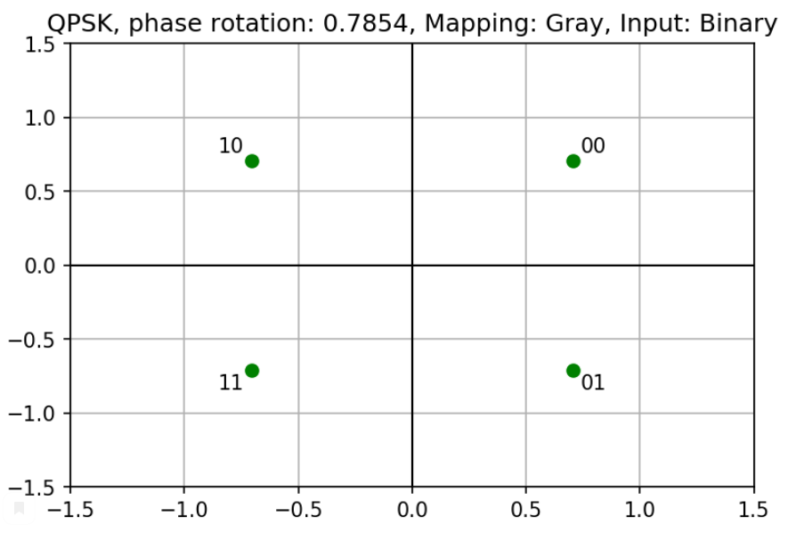
E.g. 16-QAM with decimal input and Gray mapping
modem = QAMModem(16,
                 gray_map=True,
                 bin_input=False)

modem.plot_const()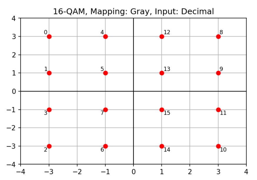
To modulate and demodulate use modulate() and demodulate() methods.
The method modulate() has the one input argument:
- decimal or binary stream to be modulated (
1-D ndarray of ints).
The method demodulate() has the two input arguments:
-
data stream to be demodulated (
1-D ndarray of complex symbols) and -
additive noise variance (
float, default is 1.0).
E.g., QPSK (binary input/output):
import numpy as np
from ModulationPy import PSKModem

modem = PSKModem(4, np.pi/4,
                 bin_input=True,
                 soft_decision=False,
                 bin_output=True)

msg = np.array([0, 0, 0, 1, 1, 0, 1, 1]) # input message

modulated = modem.modulate(msg) # modulation
demodulated = modem.demodulate(modulated) # demodulation

print("Modulated message:\n"+str(modulated))
print("Demodulated message:\n"+str(demodulated))

>>> Modulated message:
[ 0.70710678+0.70710678j  0.70710678-0.70710678j -0.70710678+0.70710678j
 -0.70710678-0.70710678j]

 >>> Demodulated message:
[0. 0. 0. 1. 1. 0. 1. 1.]
E.g., QPSK (decimal input/output):
import numpy as np
from ModulationPy import PSKModem

modem = PSKModem(4, np.pi/4,
                 bin_input=False,
                 soft_decision=False,
                 bin_output=False)

msg = np.array([0, 1, 2, 3]) # input message

modulated = modem.modulate(msg) # modulation
demodulated = modem.demodulate(modulated) # demodulation

print("Modulated message:\n"+str(modulated))
print("Demodulated message:\n"+str(demodulated))

>>> Modulated message:
[ 0.70710678+0.70710678j -0.70710678+0.70710678j  0.70710678-0.70710678j
 -0.70710678-0.70710678j]

 >>> Demodulated message:
[0, 1, 2, 3]
E.g., 16-QAM (decimal input/output):
import numpy as np
from ModulationPy import QAMModem

modem = PSKModem(16,
                 bin_input=False,
                 soft_decision=False,
                 bin_output=False)

msg = np.array([i for i in range(16)]) # input message

modulated = modem.modulate(msg) # modulation
demodulated = modem.demodulate(modulated) # demodulation

print("Demodulated message:\n"+str(demodulated))

>>> Demodulated message:
[0, 1, 2, 3, 4, 5, 6, 7, 8, 9, 10, 11, 12, 13, 14, 15]Let us demonstrate this at example with the following system model:
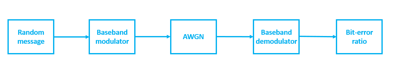
Fig. 1. The structural scheme of the test communication model.
The simulation results will be compared with theoretical curves [5]:
where ,
denotes the complementary error function,
is the energy per one bit, and
is the noise spectral density.
In case of BPSK and QPSK the following formula should be used for error probability:
The results are presented below.
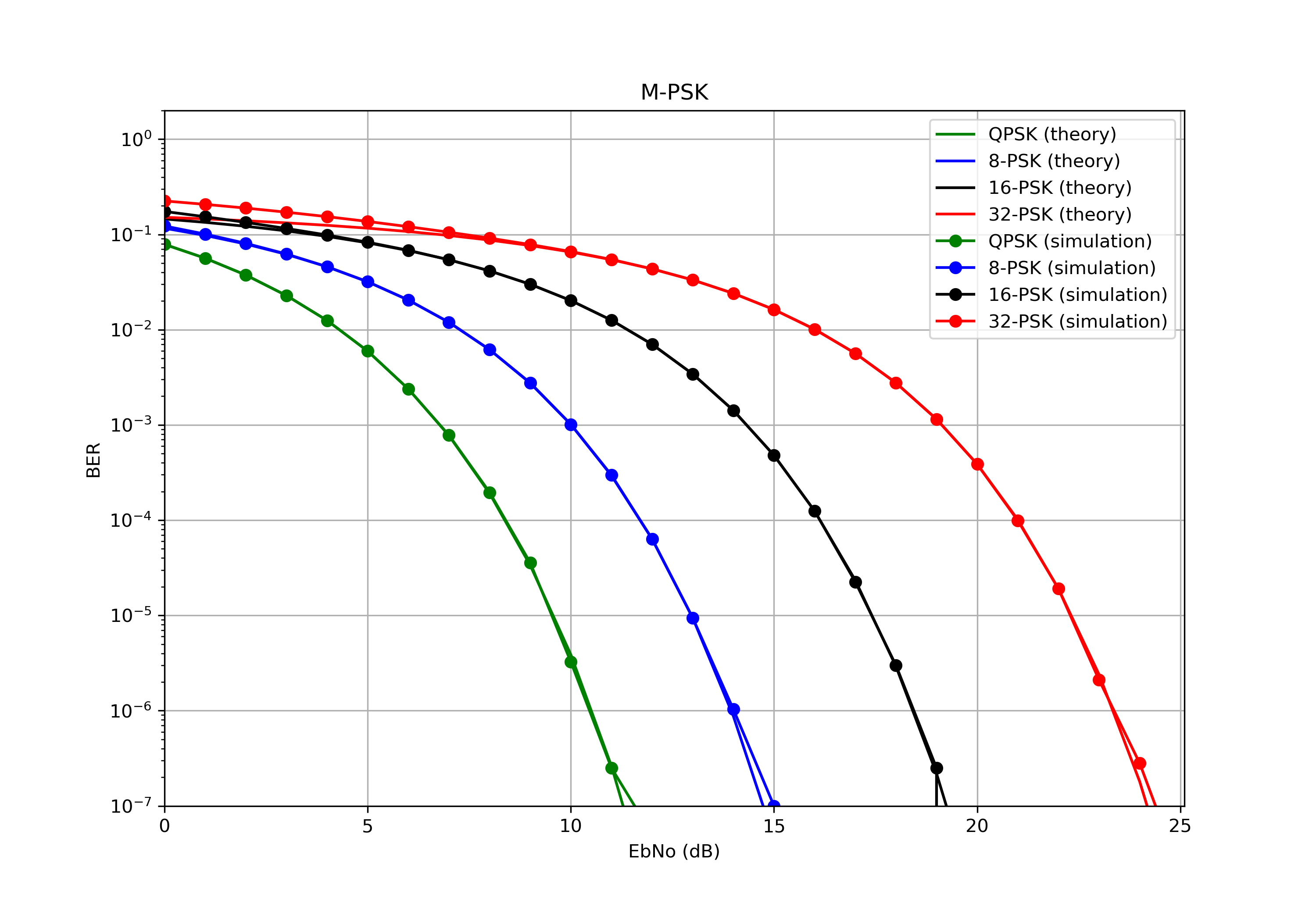
Fig. 2. Bit-error ratio curves in presence of AWGN (M-PSK).
The theoretical BER curves for M-QAM case can be obtained via the following formula [5]:
The theoretical BER curve for 4-QAM is identical to the BPSK/QPSK case.

Fig. 3. Bit-error ratio curves in presence of AWGN (M-QAM).
The source codes of the simulation are available here: M-PSK, M-QAM.
The dismatchings are appeared cause of small number of averages. Anyway, it works.
To demonstrate execution time performance let us comparate our package with another implementation, e.g. with the mentioned above CommPy.
The demodulation algorithm is developed according to following fomula in our project [6],[7]:
where is the In-phase coordinate of the received symbol,
is the Quadrature coordinate of the received symbol,
is the In-phase coordinate of ideal symbol or constellation point,
is the Quadrature coordinate of ideal symbol or constellation point,
is the ideal symbols or constellation points with bit 0, at the given bit position,
is the ideal symbols or constellation points with bit 1, at the given bit position,
is the transmitted bit (one of the K bits in an M-ary symbol, assuming all M symbols are equally probable,
is the noise variance of baseband signal.
Comparison information:
- The script: CommPy_vs_ModulationPy.ipynb
- Platform: https://jupyter.org/try (Classic Notebook)
- The frame length: 10 000 (bits)
Results:
| Method (package) | Average execution time (ms) |
|---|---|
| modulation (ModulationPy): QPSK | 10.3 |
| modulation (CommPy): QPSK | 15.7 |
| demodulation (ModulationPy): QPSK | 0.4 |
| demodulation (CommPy): QPSK | 319 |
| modulation (ModulationPy): 256-QAM | 8.9 |
| modulation (CommPy): 256-QAM | 11.3 |
| demodulation (ModulationPy): 256-QAM | 42.6 |
| demodulation (CommPy): 256-QAM | 22 000 |
Yes, I admit that our implementation is slower than MatLab blocks and functions (see "Examples"). However, I believe that this is a good start!
- Haykin S. Communication systems. – John Wiley & Sons, 2008. — p. 93
- Goldsmith A. Wireless communications. – Cambridge university press, 2005. – p. 88-92
- MathWorks: comm.PSKModulator (https://www.mathworks.com/help/comm/ref/comm.pskmodulator-system-object.html?s_tid=doc_ta)
- Octave: qammod (https://octave.sourceforge.io/communications/function/qammod.html)
- Link Budget Analysis: Digital Modulation, Part 3 (www.AtlantaRF.com)
- Viterbi, A. J. (1998). An intuitive justification and a simplified implementation of the MAP decoder for convolutional codes. IEEE Journal on Selected Areas in Communications, 16(2), 260-264.
- MathWorks: Approximate LLR Algorithm (https://www.mathworks.com/help/comm/ug/digital-modulation.html#brc6ymu)