- 🎯 Objectives
- ✖️ Multiplication Process
- 📓 Definition of the Data-Path
- 🕹️ Definition of the Control Unit
- 🔲 General Scheme of the Multiplier
- 🛠️ Implementation on the Board
The general objective of this project is to create a serial multiplier and implement it on the DE10-Lite board. The multiplier will take two 4-bit data (X and Y) and multiply them.
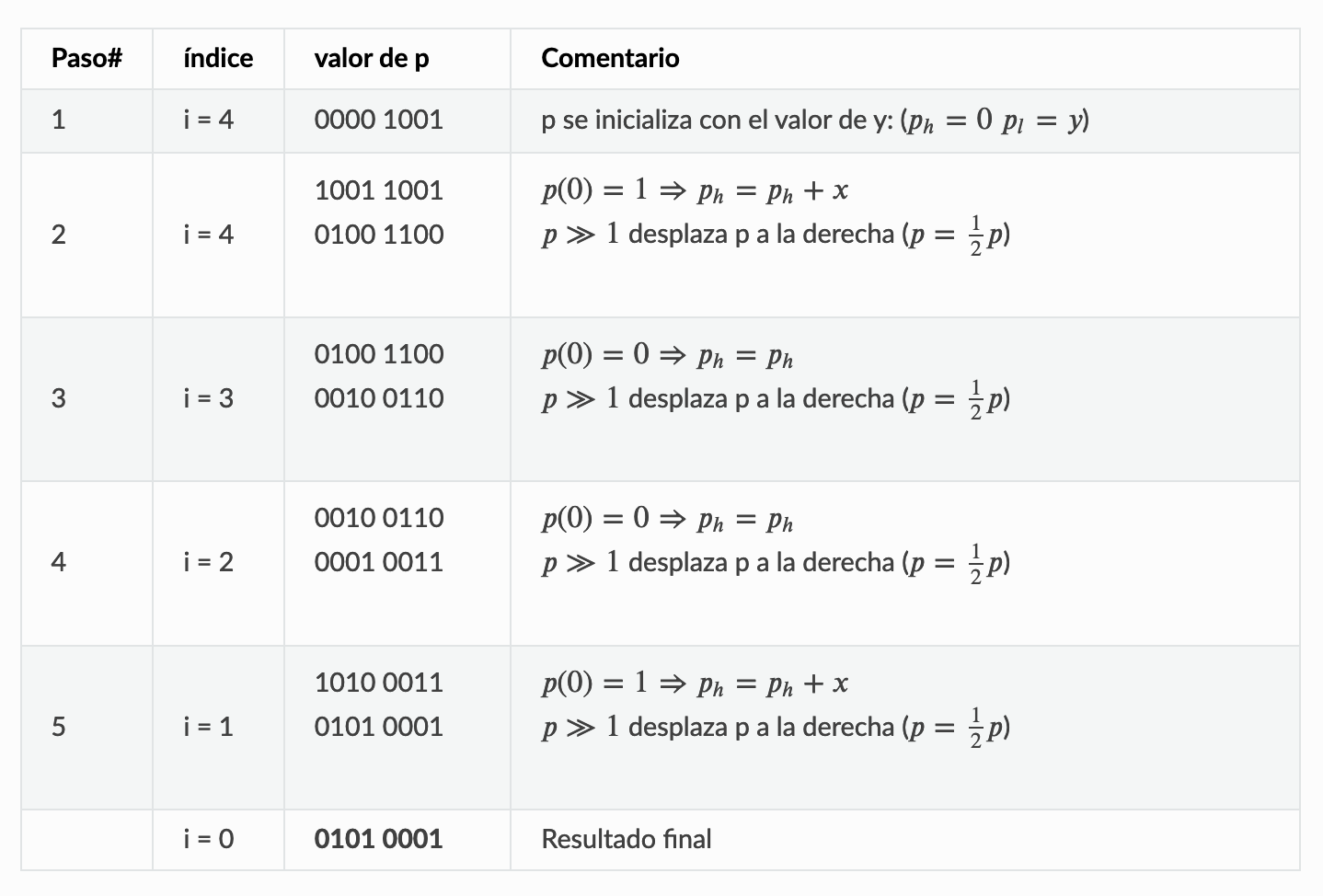
The result will consist of a "high part" and a "low part" of 4 bits each, and the union of both parts will be the final number. To obtain this value, the following algorithm is used:
- At the start of the operation, the high part is assigned 0, and the low part is assigned the value of Y.
- If the least significant bit of the low part is 0, a right shift of the high part is performed by adding a 0 at the beginning, resulting in a 5-bit number.
- Otherwise, the same operation is performed, but the value of X is added to the high part.
- This algorithm must be repeated a total of 4 times (excluding initialization) and is performed by the ALU.
The circuit to implement these operations will consist of 2 registers that store X and the final result, the arithmetic logic unit, and 2 multiplexers that will join the high and low parts, forming the following block diagram:
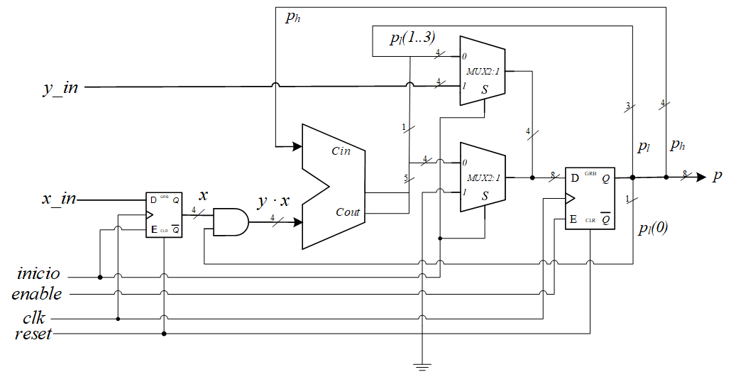
And how do we control the steps that the data-path has to take? The end of the multiplication is managed by an output signal done that is set to 1 when it finishes. In the VHDL description, you need to add a counter not shown in the image. This counter is already defined to count up to 4, so you connect its RCO, fin_cuenta, to the output signal to set it to 1 when it finishes counting.
The control unit of the multiplier will be implemented through a FSM following the following state diagram:
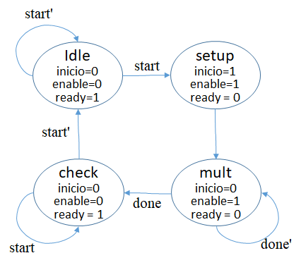
It generates the signals to start the product (start) and initiate the multiplication process (enable). The aforementioned counter starts counting in the mult state, so its enable must be set to 1 when start and enable have the corresponding values.
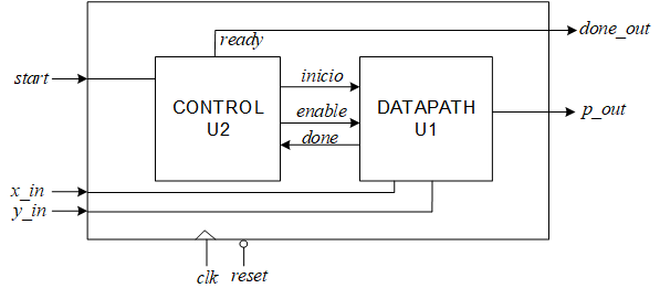
The multiplier circuit will consist of the control unit and the data-path unit, as shown in the following image:
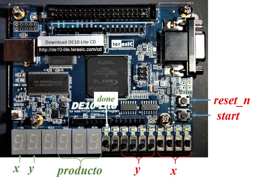
We will add the utils-display folder to the project, which contains the files to represent the data in BCD. Declare TrabajoPR1_multiplicador.vhd as the top-level entity, defining the LEDs that should light up on the board. Then, assign the pins by importing the file TrabajoPR1_multiplicador.qsf, and it is important that it is located within the working folder. The pin connection is shown in the following image:
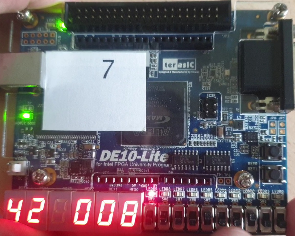
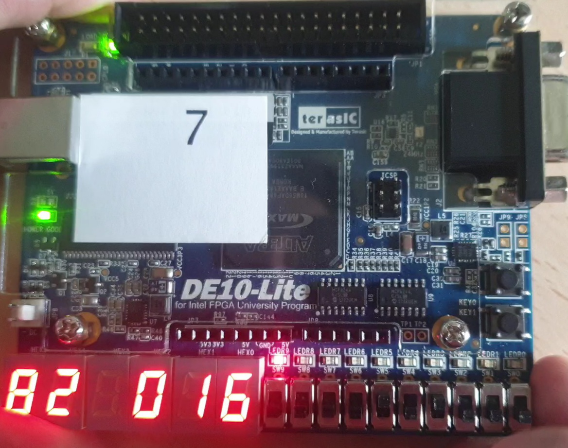
| 4 X 2 | 8 X 2 |
|---|---|
 |
 |