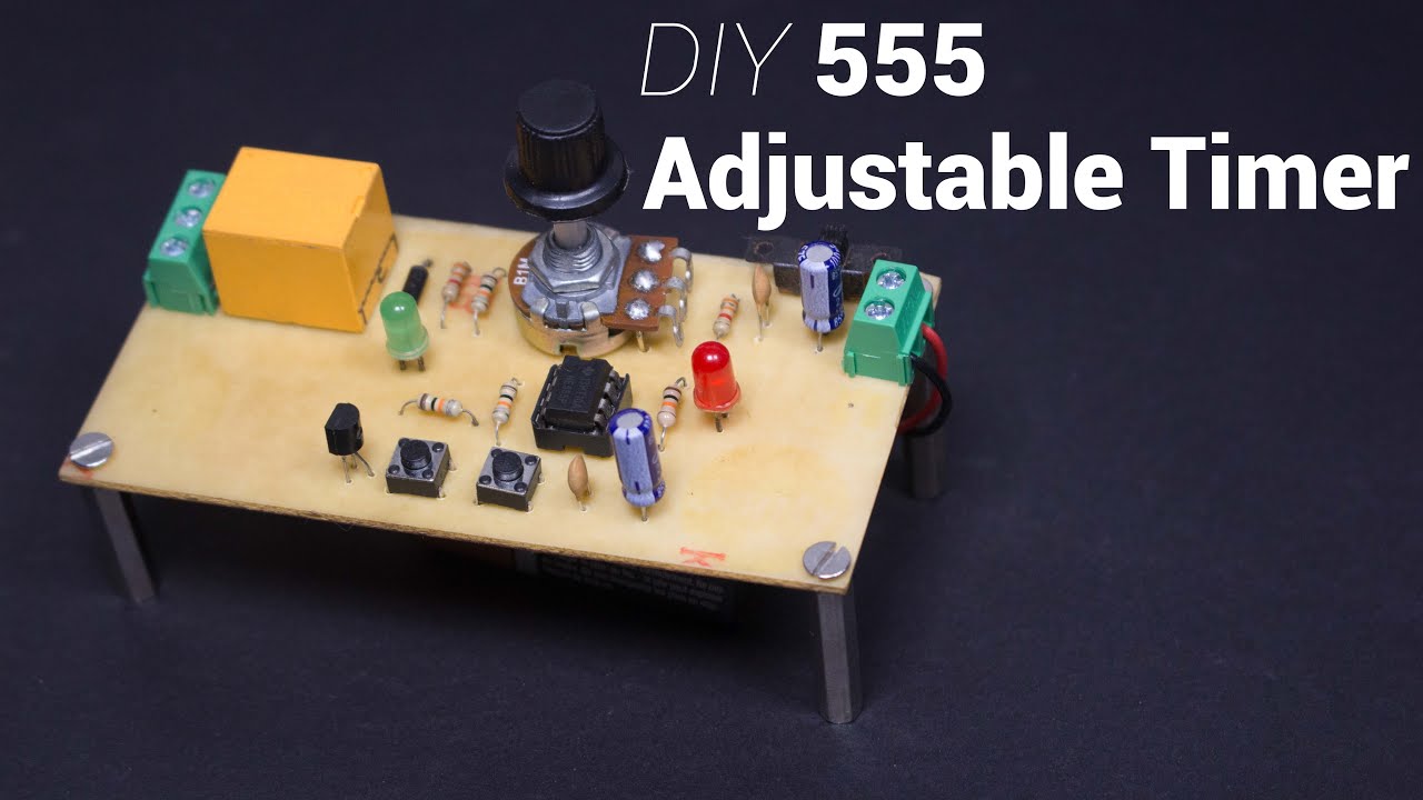
Turn a device ON for a period of 1 to 100 seconds using a 555.
Full Video:
Order PCB: PCBWay
| Qty | Component | Buy |
|---|---|---|
| 1 | 555 | AliExpress |
| 2 | 3KΩ Resistor | AliExpress |
| 4 | 10KΩ Resistor | AliExpress |
| 1 | 1MΩ Potentiometer | AliExpress |
| 1 | IN4004 Diode | AliExpress |
| 2 | Tactile Momentary Push Buttons | AliExpress |
| 2 | 5mm LED | AliExpress |
| 2 | 100uF Capacitor | AliExpress |
| 2 | 0.1uF (100nF) Capacitor | AliExpress |
| 1 | 2 Pin Screw Terminal | AliExpress |
| 1 | 3 Pin Screw Terminal | AliExpress |
| 1 | 12VDC Relay | AliExpress |
| 1 | 12VDC Adapter | AliExpress |
| 1 | SPDT Slide Switch | AliExpress |
| 1 | PCB | AliExpress |
| Tools | Buy |
|---|---|
| Soldering Iron | AliExpress |
| Soldering Wire | AliExpress |
| Mini PCB Hand Drill + Bits | AliExpress |
| Wire Cutter | AliExpress |
| Wire Stripper | AliExpress |
| Soldering Helping Hands | AliExpress |
LM555/NE555:
The 555 is a highly stable device for generating accurate time delays or oscillation. Additional terminals are provided for triggering or resetting if desired. In the time delay mode of operation, the time is precisely controlled by one external resistor and capacitor. The circuit may be triggered and reset on falling waveforms, and the output circuit can source or sink up to 200mA or drive TTL circuits.


Circuit:
In the Monostable mode, the LM555 timer acts as a one shot pulse generator. The pulses being when the LM555 timer receives a signal at the trigger input that falls below a 1/3 of the voltage supply. The width of the output pulse is determined by the time constant of an RC network. The output pulse ends when the voltage on the capacitor equals 2/3 of the supply voltage. The output pulse width can be extended or shortened depending on the application by adjusting the R and C values.
The external capacitor is initially discharged by a transistor inside the timer. Upon application of a negative trigger pulse of less than 1/3 VCC to pin 2, the internal flip-flop is set which both releases the short circuit across the capacitor and drives the output high.
The voltage across the capacitor then increases exponentially for a period of t = 1.1RC , at the end of which the voltage equals 2/3 VCC. The internal comparator then resets the flip-flop which in turn discharges the capacitor and drives the output to its low state.

The figure above shows the waveforms generated in this mode of operation. Since the charge and the threshold level of the comparator are both directly proportional to supply voltage, the timing interval is independent of supply.

Separate input triggers are used to start and reset the timer. The RC network determines the period of the output pulse. High power appliances can be controlled through a relay acting as a switch.

The LM555 has a maximum typical supply voltage rating of 16V while the relay's armature coil is enabled at 12V. Hence a 12V power supply is used to minimize the number of components such as linear voltage regulators. When pin 2 of the LM555 is triggered (by shorting it to ground) through the momentary switch S1, the timer is started.
The timer generates an output pulse with an ON time period determined by the RC network i.e t = 1.1RC . In this case, the fixed value of the capacitor is 100uF. The value of R consists of a 10KΩ resistor in series with a 1MΩ potentiometer. We can vary the potentiometer to change the time period of the output pulse.
For example, if the potentiometer is set to 0Ω, the value of R is equal to 10KΩ. Hence t = 1.1 x 10K x 100u = 1 second.
But if the pot is set to 1MΩ, the value of R is equal to 1MΩ + 10KΩ = 1010KΩ. Hence t = 1.1 x 1010K x 100u = 100 seconds.
When pin 4 of the LM555 is triggered (by shorting it to ground) through the momentary switch S2, the timer is reset.
When the timer starts, the relay turns ON. Hence the Common(COM) terminal of the relay is shorted to the Normally Open (NO) terminal. A high power load can be connected to this terminal such as a light bulb or water pump. A transistor Q1 acts as a switch an ensures sufficient drive current is provided to the relay. Diode D1 acts as a flyback diode which protects the transistor Q1 from voltage spikes caused by the relay coil.
LED2 turns on in order to indicate when the relay is turned ON. LED1 indicates the circuit is powered ON. An SPDT switch S3 is used to switch the circuit ON. Capacitors C2 and C4 are used to filter noise in the supply line.
Are you an engineer or hobbyist who has a great idea for a new feature in this project? Maybe you have a good idea for a bug fix? Feel free to grab our code & schematics from Github and tinker with it. Don't forget to smash ⭐️ & the Pull Request button.


