A sketch for the Arduino Mega that allows it to read and write to some older generation SRAM chips
The SRAM Read/Write Sketch sets up a set of control lines (WE/Write Enable, OE/Output Enable, and CE/Chip Enable) followed by an address bus and a data bus and sends the proper signals to interface the Arduino Mega to an older generation 28-pin SRAM chip. The chip in this case is the UM61256AK-15 and the datasheet can be found here: UM6126AK-15 Datasheet
Other 28-pin DIP SRAM chips should be compatible as well such as the N341256P-20: N341256P-20 Datasheet
There are three parts to the actual program itself, the initializing code that sets up the necessary control lines and busses, the functions necessary for reading and writing, and the memory testing algorithm which doesn't actually thoroughly test the chip itself but simply writes a byte and attempts to read it back, as a way of testing if the read/write functions work. Their method of operation is described below:
- In order to save keystrokes and improve readability, the
digitalWrite()functions needed to send the signals out of the control line are defined in the very beginning asOE_LOW,CE_LOW,WE_LOW, andWE_HIGH - The Serial Port is open at 9600 Baud to transmit Read/Write status to the Serial Monitor in the Arduino IDE
- Pins 53, 52, and 51 of the Arduino Mega are set as output through the Port B Register for the control lines
- Pins 22-29 are set as output through the Port A register and are part of the lower byte for addressing
- Pins 37-31 are set as output through the Port C register and are part of the uppper byte for addressing
- It should be noted that the entire byte of the register isn't used as there are only 15 address lines
Due to the fact that the data bus will have to flip between Input and Output there isn't much to set up for it and its status will be set up and changed through the Read Write functions
There are two main functions, write_data() and read_data(). write_data() relies on another function known as set_addr
which sets the proper address and data_op() which, given the proper arguments, will send data through the data bus.
read_data also relies on the same functions but with different arguments.
set_addr()
Argument:
uint16_t address- 16 bit unsigned integer that holds address to be outputted
- The first half of the address is set to PORTA (Lower Address Byte) and is outputted
- The address is shifted 8 bits so that the second half of the address is set to PORTC(Upper Address Byte) and outputted
data_op()
Arguments:
char rw- Takes the character 'r' for "read" or 'w' for "write"uint8_t data- 8 bit unsigned integer that holds data to be written
- If the
char rwargument is set to 'w' a write operation is performed - The pins of the L Port Register are set to output
- the contents of
uint8_t dataare set to the L Port register, effectively setting them on the data bus - the contents of the L Port register are returned (just as verification)
- If the
char rwargument is set to 'r' a read operation is performed - The L Port Register is entirely cleared
- The pins of the L Port register are set to input
- The contents of the L Port register are returned
write_data()
Arguments:
uint16_t address- 16 bit unsigned integer that takes in the address of the memory location to be writtenuint8_t data- 8 bit unsigned integer that holds the data to be written
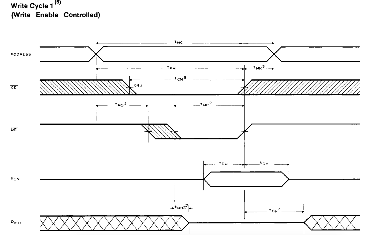
- OE (Output Enable) is set low for the duration of the function
- CE (Chip Enable) is set to low for the duration of the function
- WE (Write Enable) starts of high
- A 1 ms delay is put in place to ensure all signals are LOW/HIGH enough
- this can be removed without any problems according to my tests
- The address is sent using the
set_addr()function with theuint16_t addressargument of this function inputted as its argument - WE is set low
- The
data_op()function is called with the arguments 'w' to signal a write operation and the data from this functions argument - WE is set high
The timing diagram better illustrates the reasons for setting all these signals high or low and can be seen below
read_data()
Arguments:
uint16_t address- 16 bit unsigned integer that takes in the address of the memory location to be read
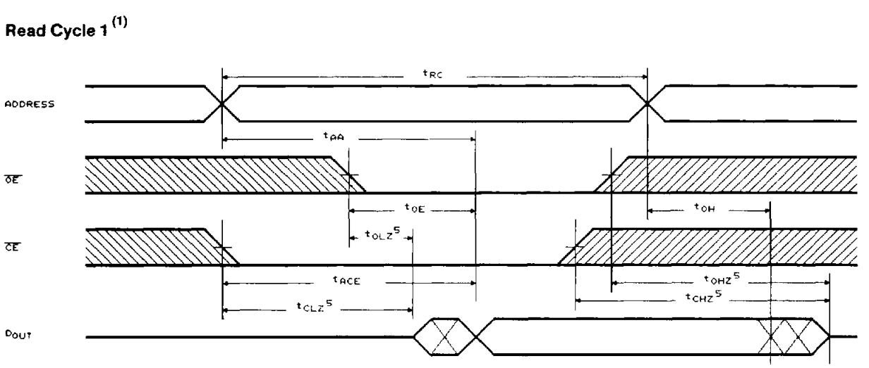
- WE (Write Enable) is set to high for duration of the function
- OE (Output Enable) is set to low for duration of the function
- CE (Chip Enable) is set to low for duration of the function
- the
set_addr()function is called with its argument the address being the argument of this function - The data read is returned by using
return()in conjunction with thedata_op()function and the arguments 'r' indicating a read operation and 'NULL' for the data to be written as no data will be written
The timing diagram better illustrates the reasons for setting all these signals high or low and can be seen below
As mentioned before, this is by no means a thorough testing algorithm and is just something to show how all the functions presented would work in a real program
- Variable
uint16_t addressis declared and unitialized - Variable
uint8_t random_datais declared and unitialized - The random number generator seed is chosen by a random read of the Analog I/O pin A0
- A "for" loop is set up that increments the
uint16_t addressvariable up to 0x7FF- For each cycle, the
random_datavariable is set to some random number between 0x00 and 0xFF. - The
write_data()function is called with the argumentsaddressandrandom_data - an "if" statement is put in place that calls
read_data()withaddressas an argument and tests for equality withrandom_data- If the data read and the data randomly generated previously are the same, the Address and Data written are displayed along with the string "STATUS: PASS"
- If the data read and the data randomly generated previously are NOT the same, the information above is printed but with the string "STATUS: FAIL"
- For each cycle, the
- A 500 millisecond delay is put in place to ensure that all the data from the Arduino is properly received and displayed on the Serial Monitor
- The program is terminated using the
exit()function
These are a couple of improvements I'd like to make to the program itself or just some things that I've been running through my head.
- Adapt code for the Arduino UNO using shift registers to save on pin space
- Add a blinking status light during I/O Operations
- Possibly implement a more robust memory testing algorithm