Tutorials
The structure of the tutorials directory included in this repository is similar to the official OpenFOAM releases and is shown below:

The tutorials are provided with multiple mesh files identified by a .msh extension. These files, generated either using GMSH or ANSYS FLUENT, are named according to the convention below.
<tutorial_name>_<number_of_cells>.msh
The user can choose which mesh to use by specifying it in the runParameters file located in the constant directory.
meshFile twistingColumn_384.msh;
Additionally, in tutorials where the mesh is generated using GMSH, the GMSH geometry source file (*.geo) is also provided. This gives flexibility to change mesh size according to needs.
Note that the tutorials in this repository are configured to be executed on a single core. This is specified in the decomposeParDict file located in the system directory.
numberOfSubdomains 1;
Multiple cores could be used for the simulation simply by specifying a higher number for the subdomains. This is accompanied by appropriate inputs for the domain decomposition methodologies offered by OpenFOAM.
In order to setup and simulate the problem every tutorial is provided with a run script. This script will take into account whether a single or multiple core simulation is requested, convert mesh to OpenFOAM format and generate initial conditions if needed. The script can be executed by typing the following inside the tutorial directory.
./run
The solver output is directed to the log file written as
log.<solver_name>
The solver output is also displayed on the terminal screen for a single core run. However, in the case of a parallel run, the solver runs in the background. Therefore, to see the solver output on the fly type
tail -f log.<solver_name>
OpenFOAM comes with the paraFoam script that launches ParaView for post-processing. This script can be executed as
paraFoam
Note that in the case of a parallel simulation, the results need to be reconstructed before to allow visualization of the whole domain. This can be done as
reconstructPar -withZero
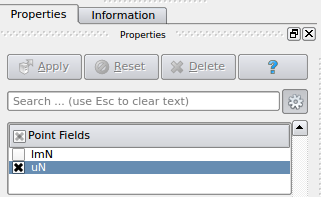
In ParaView, load the nodal displacement field uN (or u in the case of vertex-centred code) under Point Fields in the properties toolbar.
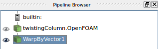
Now apply the Warp By Vector filter to move the mesh according to the nodal displacements.
The VCR controls in ParaView can then be used to visualise the deformation along with cell-wise (or node-wise for vertex-centred code) pressure distribution.
All tutorials are provided with a clean script which deletes the output of a previous run in preparation for a fresh simulation and can be executed as follows
./clean